Back to Squarebirds.org


  From: Tony & Liz
  May 11, 2011
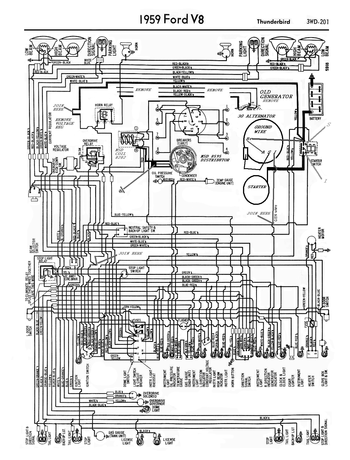
  Subject: Wiring changes from old 1959 Thunderbird generator system to Ford 3G Alternator
 
  I have tried to change the old wiring diagram, to explain it a little.
  I have not wired under the hood yet .
 
  My questions are
  1. The terminal from the "I" circuit; do I just wire it straight to the Generator light, or do I need to couple it
        to the "I" side of the starter switch on the guard?
 
  2. If I leave the large power supply wire to the removed voltage regulator to power the horn relay is this safe?
 
  3. Where do i pick up the power supply for my electric choke (needs to be 12 volts and no less)?

ANSWERS:

  1. This wire is very important!  Without it, your alternator will not sense your key is on and will not
     output!
     
This simple task sounds harder than it is.  We don't want your alt to stop working because of a
      broken light bulb filament so we install a resistor around the lamp wires.

      Your original "GEN" light wire went to the Voltage Regulator (on the Armature post).   If you leave
     that black\red wire on the regulator it will GROUND OUT your 'sense wire' on your new alt. Remove
      that Yellow/Black wire from your voltage regulator. Splice it to your new alternator and connect it
     to the '
I' terminal ('I' stands for IGNITION power not start). At the GEN lamp
     socket, solder or crimp a 560-ohm resistor across both wires. 560-ohms conveniently works out
     to 1/4-watt, so use a 1/2-watt resistor (or two 1/4-watt 1.2k-ohm resistors in parallel). 

     The purpose is to signal the alternator that the ignition is turned on. If your alternator stops turning
     (like when you first turn the key on, or if you ever throw a belt), the GEN light will shine.

  2. Sure it's safe.  It's also a good place for new components to feed from like an electric fan relay or
      a halogen headlight relay, or any relay (see #3).

  3. Use your ballast resistor wire from your ignition switch. It is on and it already comes into the
      engine bay.  Connect it to a relay coil so the contacts will close as soon as you turn the key on. 
     Connect one relay contact to a battery connection, and the other side of that contact to your
     electric choke.
      Again, we are trying to lighten the load on your key switch and eliminate additional heavy wires,
      going to your dash.  This 'power relay' works well for a Pertronix system, too.


(Click on the images below for a printable size.)
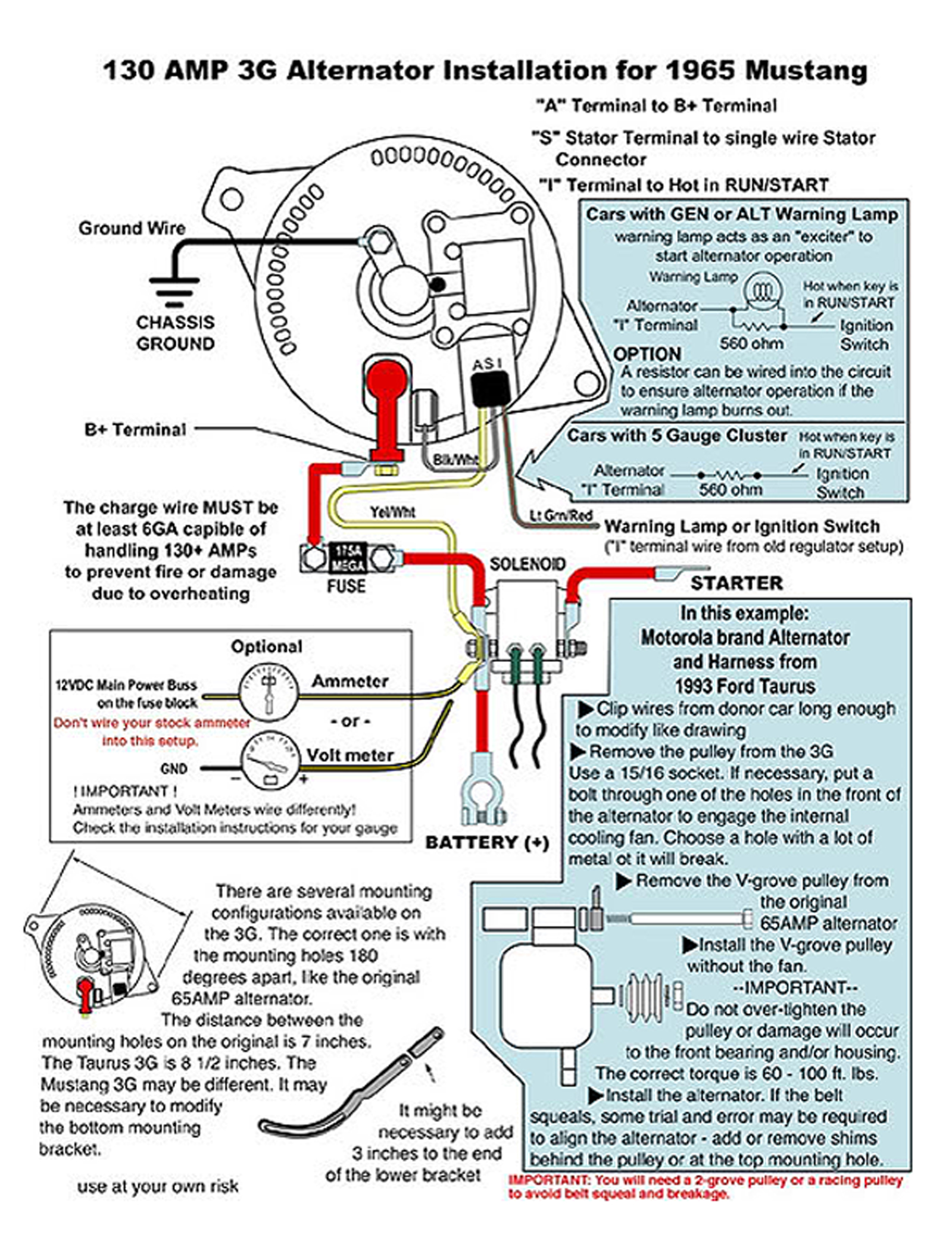
#1
 The above diagram explains the need for #6-AWG copper stranded wire to carry the high current, and it
includes a fuse.  The fuse is VERY important.  If one of your diodes ever shorts inside the new alternator, your
battery will unload as much current to ground as possible in the shortest amount of time.  This burns your wires and
leaves a dead battery (or just a blown fuse).

As shown in the drawing below:
See the yellow/white wire labeled "A"?  A more simple attachment would be to connect it to "B+" on the Alternator.

If you can't use a two-groove pulley, a larger diameter single groove pulley will work.  It has more surface area for
the 'V' belt to grab and the larger diameter gives a better 'lever', making it easier to turn.  The downside is your
engine needs to run a bit faster than idle, to produce current.

#2


Back to the Top


Back to Squarebirds.org