Most folks are familiar with using a timing light for setting spark timing. In reality, they are setting one of three different but very important parts for proper spark advance. Distributor timing is commonly misunderstood. The three parts include:
While the first two methods follow engine speed, vacuum advance senses intake manifold vacuum or gas pedal position. When your engine first starts there is NO vacuum, so no vacuum advance. At wide Open Throttle (WOT), climbing mountains, racing or just taking off from a light, there is very little or no vacuum. Vacuum advance is designed to give extra advance only at cruising speeds. Racing distributors don't use vacuum advance because the gas pedal is always down.
Every engine that is
put into different service, from when it was new, needs the
distributor set up under a load, creating horsepower. This
includes when changing your camshaft, changing compression ratio,
repurposing an engine from another vehicle, changing altitude,
adding or subtracting weight from your car, re-jetting your
carburetor, fuel pressure changes (in a fuel injected engine), etc.
A carburetor's goal is to deliver 14.7:1 air-to-fuel ratio, while a
distributor's goal is to time the fuel mixture BURN to happen at
precisely the right time. Different octane fuels burn at
different rates in different compression ratios.
A distributor re-curving machine cannot possibly simulate an engine
under load but it can help track spark advance settings through the
rpm range and show when Total Advance peaks. The rest is done
by trial and error to avoid engine knock at different ; Total Advance includes the initial
advance. For example, if we start with 6°BTDC, at idle with
the vacuum hose off, and slowly increment the speed in 500-jrpm
increments, the
timing marks should steadily advance to ~36° at 2,500-RPM and hold
there with no more increase as RPMs raise further.
Vacuum advance is totally separate as it performs a completely different function. At start, we should expect to see very little vacuum advance. As the throttle opens, vacuum goes down. When climbing hills there is very little vacuum. So vacuum advance is designed for steady throttle conditions and it adds to Total Advance.
Distributor gear material must be compatible with the cam gear metal. Factory cams are usually cast iron, so factory distributor gears are usually cast iron as well. If you buy a new cam, the manufacturer usually suggests which gear to use. In short, Cast Iron gears go with Cast Iron cams, Steel cams usually go with steel gears or bronze gears, but they will quickly eat up cast iron distributor gears. Ask your cam company which distributor gear they recommend. Remember that High Volume Oil Pumps require more gear power to run.
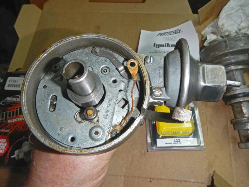
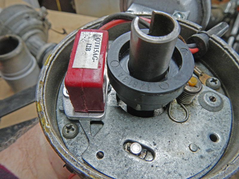
Instead of points and condenser, Pertronix Ignitor II will be installed. I start by removing the vacuum unit, points & condenser, breaker plate and the top portion of the distributor.
 #1
#1
Also remove the ground jumper and the breaker pivot plate.
 #2
#2
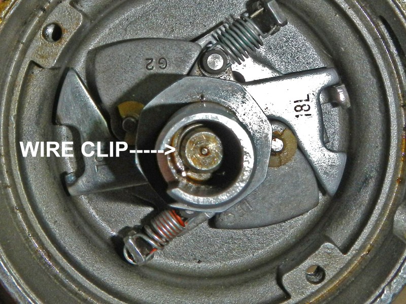
Under the rotor is a wire spring clip that secures the points cam and
reluctor arms.
Two pairs of surgical hemostats
work well to remove this clip.
 #3
#3
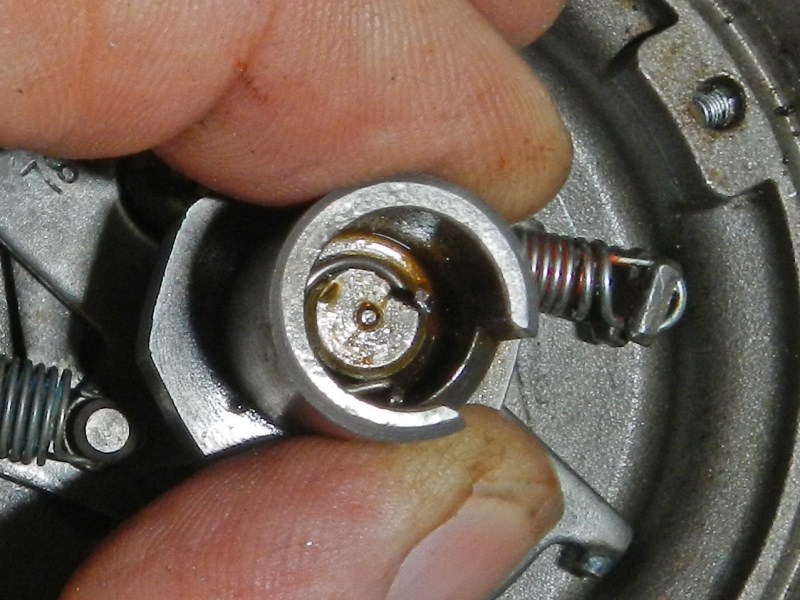
Now, the clip is dislodged and just laying
on top. Remove both advance springs and pull up
on the top center piece.
 #4
#4
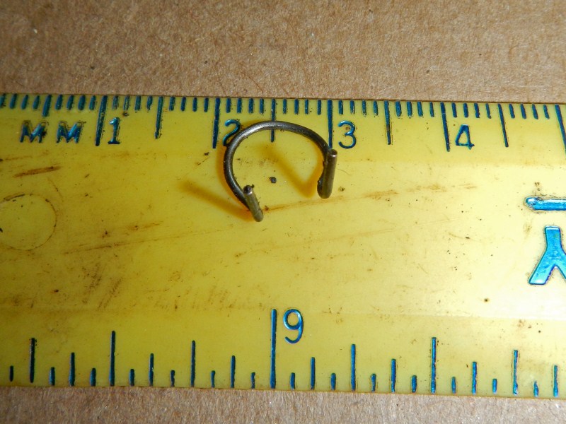
This is the spring clip. Carefully clean and set aside.
 #5
#5
They call this a Reluctor Arm. Degrease and set aside.
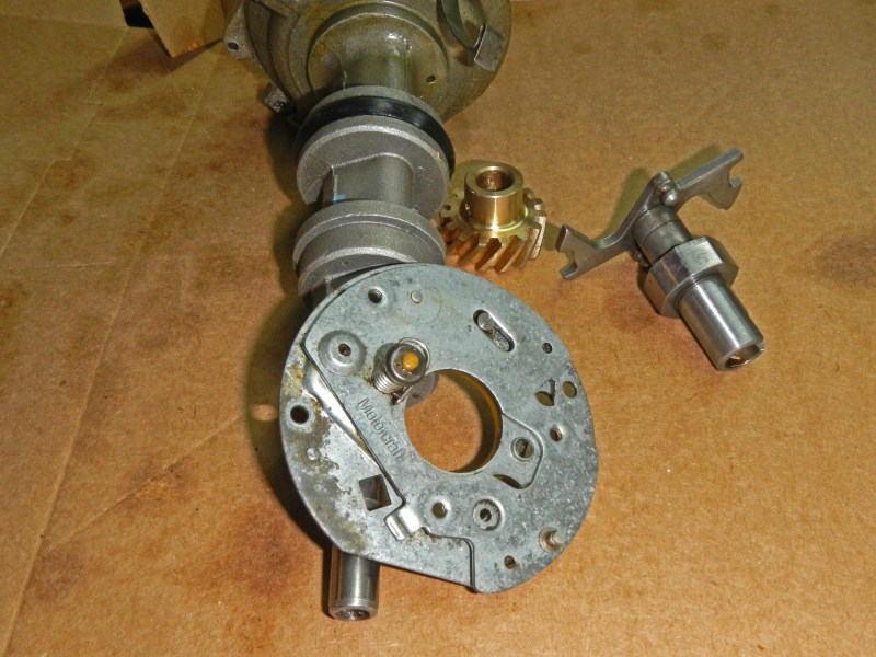 #6
#6
Use a small punch to remove the 1/8" roll pin and the cast iron
Distributor Gear. This distributor will sport a Comp Cams
bronze gear. Wash the dirt off and degrease all the parts.
Everything should slide smoothly.
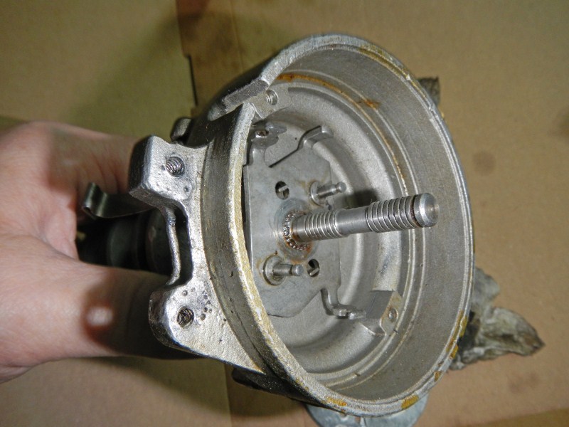 #7
#7
There is no reason to completely remove the center shaft
because these housing bearings feel good. Some
distributors need their housing bearings changed. The
center shaft comes up and out from the bottom. Some
distributors have a piece of felt just under the rotor to wick
light oil. The rings on the center shaft hold the oil.
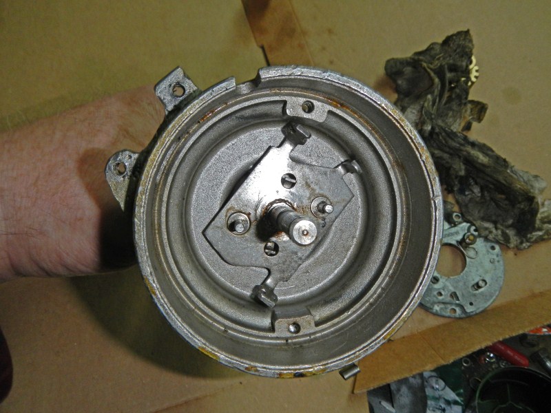 #88
#88
This is what you should end up with. Next, let's install
the new bronze gear.
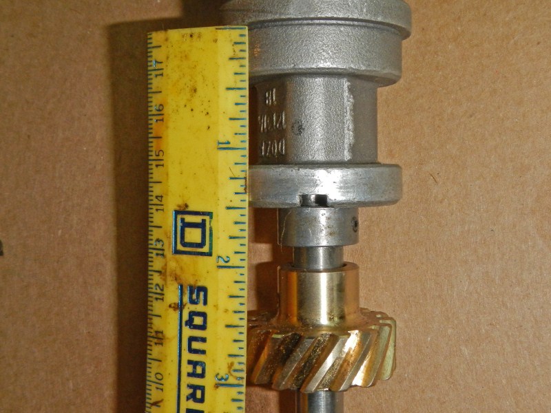 #9
#9
Measure from where the distributor rests in the block. The new gear teeth should fall between 2-1/2"
and 3" from this bottom flange. Now, it's time to pin it.
There is no real
standard for roll pin location and it seems every one is a
little different. I always drill a new 1/8" hole through
the center shaft about 10°
from the original hole alignment. You can try to match the
original holes but for me, drilling a new hole is easier and
faster.
 #10
#10
It's the real deal, straight from Comp Cams (for a tidy $50,
the bastards).
 #11
#11
The hole is drilled and the roll pin is installed.
BTW,
I want the roll pin to shear if the oil pump or drive shaft
fails. That way the engine will simply stop.
Time to set the advance on this Distributor. Correct timing can only be
accomplished with the engine running in the car with a load. How much advance? We increase advance with rpm and decrease advance with engine load. A distributor test stand cannot duplicate these characteristics
but a dyno can. All you need are some basic hand tools, a timing light, a tachometer and your engine under load. A light car needs a different advance curve than a heavy car running the same engine.
The centrifugal weights advance the timing based on engine speed. The faster the motor spins the more it will advance the timing. The factory advance curve is very conservative,
peaking at about 3,500-4,000 rpm. By using a more aggressive advance curve you can greatly improve performance
and efficiency for little or no money.
We are shooting for 36°
 #12
#12
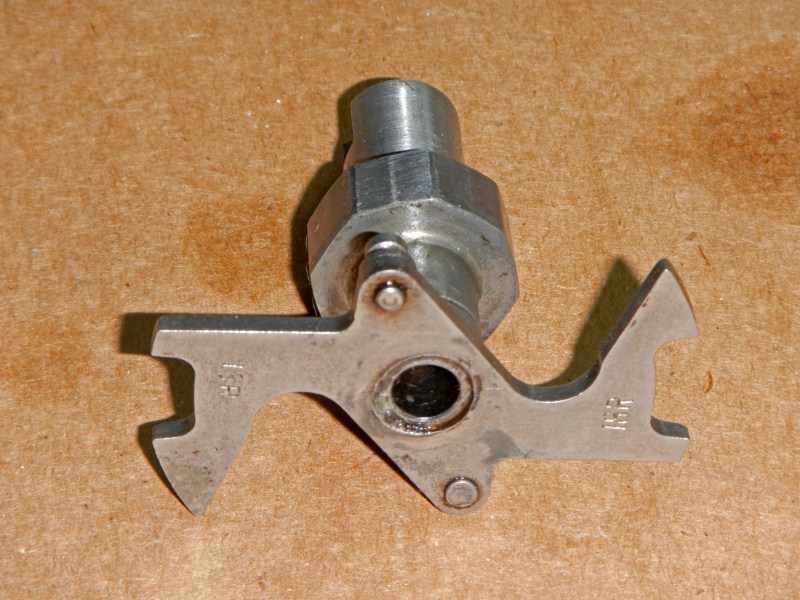
Notice the far LH side has stamped numbers (13R) next to a gap. The RH side has another number stamped (18R) next to
a wider gap. These gaps limit how far the weights can advance. Since the distributor rotates at half the crank speed, we double these numbers. So, one side represents 13x2 = 26°, and the other side represents 18x2 = 36° of advance. If we set initial timing with no vacuum advance at 10°, we ADD that to the TOTAL ADVANCE.
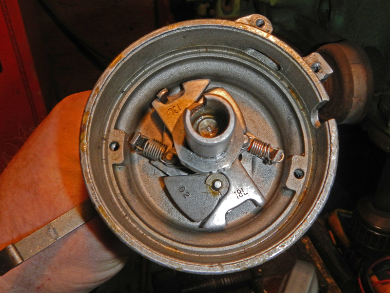
Again, we want TOTAL ADVANCE to peak at 2,500-RPM and above, so this is where the springs come into play. Normally, the lightest springs are used on both sides. Instead, I have stretched the heavy stock spring so it will do nothing until about 3/4-travel. We will see later, how this turned out.
 #13
#13
Now the Reluctor is using the '13L' setting. The next pics show different angles.
 #14
#14
 #15
#15
 #16
#16
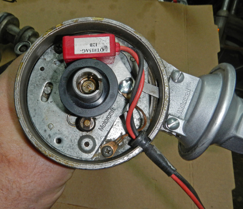
The pivot plate is assembled with the vacuum advance and new Pertronix setup.
 #17
#17
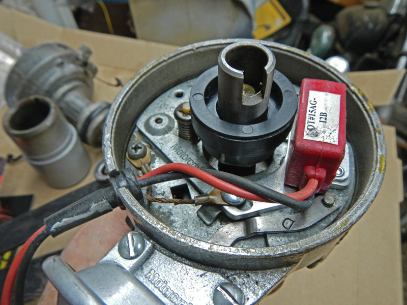
The ground wire is in place and I am showing the correct .030" gap between the pickup and rotor.
 #18
#18
Now we're ready to drop the distributor in.
Here's my method...
I rotate the crank by hand (tightening the crank bolt) while
watching #6 cylinder's rocker arms. When the exhaust valve
is coming up (nearly closed) and the intake valve just starts
down, right then, with both rocker arms 'dead level', the damper
marks should be at TDC. <--(This is the cam's top dead
center.
If the damper timing marks are about ten degrees off TDC, that
means the timing chain is off one tooth and it must be
corrected.)
Let's continue...
I point the rotor just passed #6 cylinder's rocker arms and drop
the distributor in with plenty of grease on the gear. As
the gears mesh the rotor will 'back up', landing at #6 rocker
arms. If the distributor doesn't drop all the way, the oil
pump driveshaft isn't aligned yet. Simply rotate the
damper pulley 1/3-turn or so more, keeping a little downward
pressure on the distributor and it will drop into place.
Bolt it down but keep the bolt loose.
Turn the crank again to make sure the distributor is centered
correctly with the rotor pointing at #1 spark plug tower when
the crank damper is at TDC. If the rotor points at #6
spark plug tower, wind the crank one more revolution.
Then, install the cap and wires.
Consider what just happened because it's all about timing... We set up and verified the crankshaft is properly timed with the camshaft and the cam is timed with the distributor for 'ballpark' spark plug timing. I can't count the number of times I have caught timing errors by using this method, before the timing cover was installed. It works even if the timing chain set has no timing marks or wrong timing marks. 460 engines came from the factory with the cam 15 degrees retarded. Folks were simply amazed at the stump-pulling power of their engines once properly timed.
Trial and Error:
Two major factors
affect how much advance is required, engine speed and load.
We increase advance with rpm and
decrease advance with engine load.
In addition, low octane gas burns faster, causing us to back off
our advance.
Rotating a Ford distributor clockwise advances spark.
I always set my Total Advance first, then notice where my
Initial advance fell, all without vacuum advance. Ping or
knock means too much advance. If we simply turned the
distributor, we alter both the Initial and Total Advance.
One solution is to use the larger number on the reluctor arms to
spread out the advance. If the all-in happens at 2,500,
then the Initial is backed up closer to TDC. Some guys use
the large reluctor opening and solder metal onto the stop,
making it exactly the right spread for their needs. If
pinging happens in the middle of your rpm range, use a stronger
spring.
After setting the mechanical advance, then I do the vacuum.
Vacuum Advance is tricky because there are no set numbers or
measurements. A vacuum pancake can increase Total Advance
to as much as 60°! If under load, we start to hear engine
knock, most vacuum pancakes have a set screw adjustment inside
the vacuum port. Turning it in (clockwise) will shorten
the stroke, which limits the advance.
Should you use
Ported Vacuum or Manifold Vacuum? I use manifold vacuum
because it makes my engine idle much smoother. There is no
load on the engine at idle, the cylinder pressure is lower so
the fuel mixture burns more slowly so more advance lights the
gas sooner.
CLICK HERE to return to Home Page