Ford 390 FE Engine Overhaul
1963/ FE CAMSHAFT & TIMING SET ASSEMBLY & SETUP
BACK TO HOME PAGE
 #1
#1
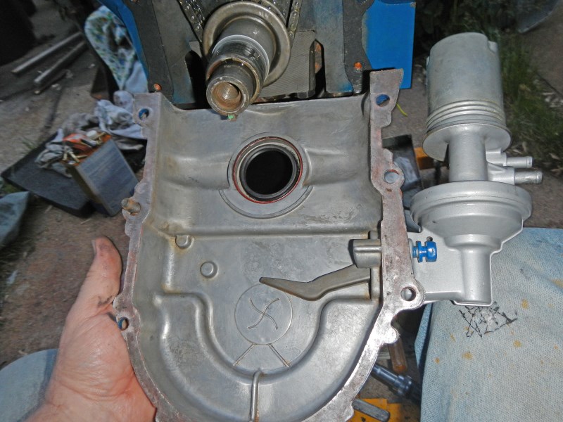
Here's the correct assembly setup
for the roller cam I am using. Previous years used the button and spring
instead of a thrust plate (6269). Ford dropped the old setup in
favor of this one. Unfortunately for older engines, parts are
limited and high in cost. Parts for these engines are plentiful
and inexpensive. I suggest if you have an old setup, you can use
this one by drilling two holes and buying the thrust plate for ten
bucks. Then, a wide array of modern cams at decent prices are
available at every speed shop.
At the time of printing,
True Double Roller Timing Sets were not on the market. They last
three times longer than conventional chains and are available at
Summitracing.com for $40.
 #2
#2
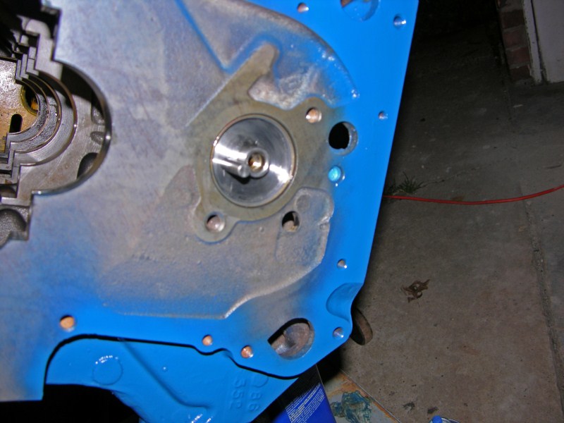
Verify the bearing
holes are properly lined-up with the block. Use
a good engine assembly lube in each cam bearing. Installing the
cam before the crank is easier because it is open from inside the block.
It's easier to take pictures, too. If your crank is already
installed, you can still install the cam.
 #3
#3
Carefully start turning and
fishing the new cam into each bearing.
 #4
#4
 #5
#5
 #6
#6
 #7
#7
Everything looks and feels
good.
 #8
#8
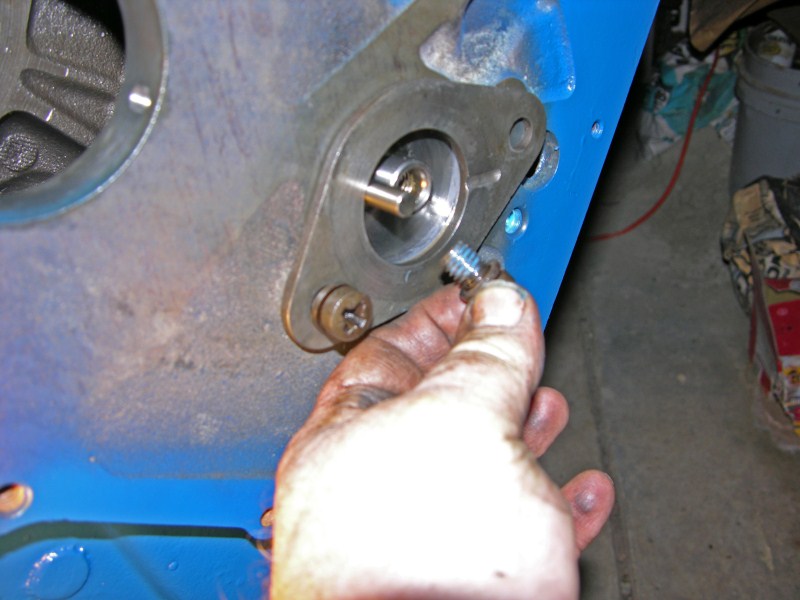
Notice I use blue
(removable) LocTite on the bolt threads.
 #9
#9
This is just a mock-up
because the crank needs to be installed before setting the chain and
sprockets. I'm showing how this will look when finished.
 #10
#10
Follow the Shop Manual
instructions for aligning the sprockets with the marks. Don't
forget to LocTite the cam bolt and torque to 45ft/lbs. Notice
the cam bolt washer holds the eccentric and it traps the locating pin from
coming out.
I'm going to kill a few
birds with one stone, here. This is how your new timing set
should look with one exception. I slid the crankshaft sleeve
on backwards (just to hold the slinger in place). Normally at
this point, a garage mechanic would wrap up this job, be done and
get paid.
But wait, how do we
know the marks are correct? What happens if a mark is missing?
How can we double check cam-to-crank timing before bolting the
covers back on? What happens if the marks are WRONG?
CHECK CAM POSITION
AGAINST THE CRANKSHAFT POSITION TO MAKE SURE THE TIMING MARKS ARE
CORRECT.
We need to put the cam
in position where it is at top dead center and see if the crankshaft
agrees. For this, we need no fancy tools, but let's use what
we know.
Let's look at the
firing order. Since this is a four-cycle engine, let's connect the
firing order using two lines:
1 5 4 2
| | | |
6 3 7 8
When #1 is in its power stroke, #6 is in its exhaust
stroke. Both pistons move up & down together. More specifically, half way between when #6 closes
it's exhaust valve and opens it's intake valve, right when these two
lifters are dead even, #1 should be at TDC.
I advanced my cam by just
a small amount. Let's see how the degree wheel verifies this.
Notice I bent and
mounted a coat hanger as a temporary pointer.
I need to find TDC on the crankshaft.
 #11
#11
I pulled #1 (or #6)
spark plug and screwed a Piston Stop in the hole. Then I installed my
old trusty degree wheel. It doesn't matter where the wheel
location is,
as long as it's tight on the bolt.
BTW, you can download a
free degree wheel from the net, print it out and glue it to shirt
board.
I ran the crank around
until it stopped. Then I made my first chalk mark on the
degree wheel.
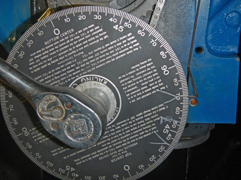
#12
Then, I ran the crankshaft around the opposite direction until it
stopped. Exactly between my marks is my center line or
true TDC. At this point,
remove the Piston Stop
and store it away.
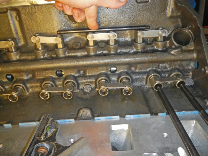 #13
#13
Ok, I rotated the crank until these Morel roller lifters are exactly in between
exhaust and intake strokes as described.
You can use a 'straightedge' at the lifters or at the rocker arms.
For this picture, I'm using a pushrod for a 'straightedge'.
 #14
#14
Look where the pointer landed. It's about 5 crank degrees
before my centerline. That means the cam is advanced about
2-1/2 degrees. That's right where I want the cam, advanced
anywhere between two and four degrees. That brings my torque
curve toward low-to-mid range for more power and efficiency at street and cruising
speeds. If this roller chain ever stretches, timing will go toward zero
advance or 'factory setting'.
 #15
#15
Now that we know it's right, time to pull the crank sleeve off and
install the timing cover.
 #16
#16
After the cover is installed, slide the crank sleeve back on and
install the key.
Clean up the pointer for easier timing mark viewing.

#17
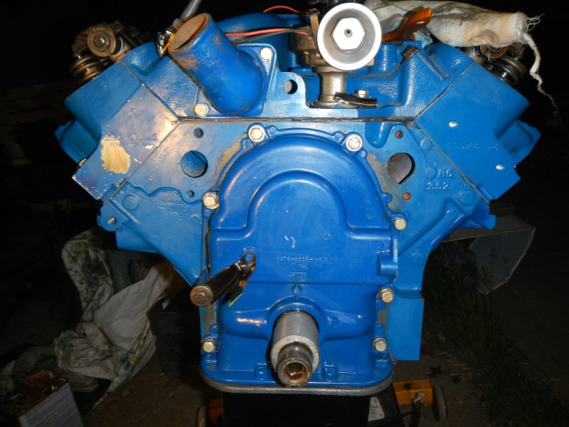
In 1973 this F-100 engine was Ford Blue. I'm painting the
block black for Penelope, a beautiful 1960 Thunderbird.
Pictures don't do well when everything is black.
 #18
#18
I don't know if this oil pan, timing cover and damper pulley will be
used, or the parts from Penelope's 352.
 #19
#19
Tighten all the bolts and she's ready to go
.
Top of
Page
CLICK HERE
to return to Home Page