 #1
#1Block assembly starts with the details. Chase all the tapped holes to make sure they are clear, deep enough and the threads feel smooth. Do this for every threaded hole in the casting. Clear the chips out by using a magnet and air.
CLICK HERE
to return to Home Page
The block is machined, main bearing caps are honed, oil
modifications are done and we're ready to assemble.
The crankshaft is balanced, pistons & rods are all matched. I
always start by chasing all the holes, then I install the camshaft
because the crankshaft is not in the way.
#1
Block assembly starts with the details. Chase all the
tapped holes to make sure they are clear, deep enough and the
threads feel smooth. Do this for every threaded hole in
the casting. Clear the chips out by using a magnet and air.
 #2
#2
 #3
#3
Now, lube the cam
bearings and carefully fish the cam in place, so as not to nick the
bearings.
 #4
#4
Clean the journals well, insert the oil seal halves, insert the main
bearing half-shells and carefully lay the crankshaft in place.
 #5
#5
After checking bearing clearance on each main bearing using Plastigage, spin
the crank by hand. In fact, I do this along the entire build.
If the crank binds, stop. Go back and find the bind and fix
it. The crankshaft should be true and smooth at every ground
surface. Bearings are extremely soft. A small 'ding' in
the crank will wipe out a bearing or possibly 'spin it' in no time. If you have a
ding in the crank, locate it and carefully stone the ding out and clear all debris before
continuing. If the crank spins freely, proceed with installing the oil seal,
then check it again.
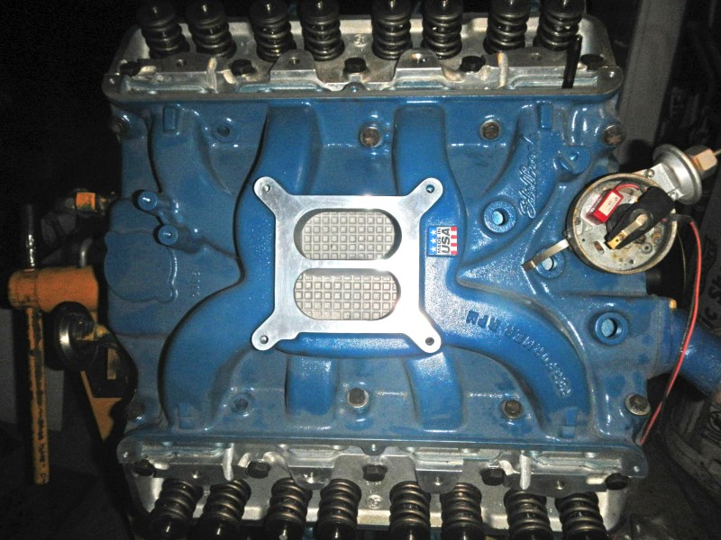
Here is the dual
plane intake with the distributor installed. That is a
Pertronix pickup inside the dizzy.
 #6
#6
Notice the black "X" marks. Since we are using +.040"
(heavier and larger) pistons, Mallory Metal was inserted and
welded into the crankshaft counterbalances. Mallory Metal
is half-again as heavy as lead but hard, like carbide steel.
Notice the surface drill holes for dynamic balancing. This
balance job was done right and the result is the best I've ever
seen. #7
#7
All piston rings must be checked in their respective bores for end gap
clearance. <--This is important!
Regardless, if your ring set is "file to fit" or "pre-sized"
doesn't matter a damn. One tight ring can ruin your bore
and/or piston, and will probably break the ring in the piston
groove (rendering it useless). Tight metal must go
somewhere. When I disassembled this
390 I
found one factory ring that was broken. The ring was new when it broke. So for the rest of this
old engine's life, all that ring did was go along for the ride
and promote more blowby. We need ALL rings to seat
properly and work hard for the next 250,000 miles.
These hypereutectic alloy pistons conduct heat faster than
ordinary pistons, so the Moly ring end gaps must be much wider than
1959 pistons. For our bore, we need .022" gap.
Use a bare piston to slide the new ring down the bore so it sits
straight, then measure the gap with a quality feeler gauge.
 #8
#8
I use a brass protection sleeve when installing rings. It
allows the ring to open 'just enough' and it keeps the ring ends
from grooving into the piston as it slides down. Twisting
or curling the new ring will bend it. Then the ring will
never seat.
 #9
#9
All rings must slide freely in their slots. If one
hangs up, correct the slot.
 #10
#10
Now that the ring set is installed, this is the last time to
check. Keep it straight in your head: The notch in the
piston top goes forward, the rod has an offset oiling hole at
the wrist pin that sits on top when the engine is installed, and
each wrist pin has two snap ring keepers. If any of this
isn't true, stop.
 #11
#11
There are several good ring compressors and sleeves for
sale. This one happens to be a Lisle. I've used it
for many years.
Piston rings turn, by design. Don't put an awful lot of
emphasis on getting the gaps in a certain orientation.
This constantly changes by itself, the same holds true for
rotating valves.
 #12
#12
Insert the bearing and lube all parts of the piston well,
before installing. I brush oil into the oil groove.
To protect from nicking the crankshaft, I use hose material over the cap studs.
The hose must be thin and easy to remove.
 #13
#13
Turn the crank so the pin is at the bottom.
This gives room for your hands to grab the rod and guide it as
you gently pound the piston in with a rubber mallet or a wooden
hammer handle.
 #14
#14
Here it comes. Work both top and bottom ends
simultaneously to align everything. If the piston needs to
turn a little, grab the ring compressor tool and turn. The
rings won't turn but the piston will, so the rod will align with
the crank.
 #15
#15
I also brush a bit of oil into the crank holes before
it is covered.
 #16
#16
At this point, get out the plastigage and measure for
clearance. BTW, you start to see oil running down the
crank. I would much rather have too much than too little
oil. Put a pan under the engine because this is going to
get worse.
 #17
#17
Yep, right in spec's. Now remove the
plastigage (which is really wax), lube the bearing and torque
the cap.
 #18
#18
After tightening, turn the crank by hand. If it feels
good, do the next seven pistons the same way.
 #19
#19
All the pistons in the Left Hand bank are properly stuffed,
clearance measured. Time to do the RH side.
 #20
#20
I only use a good quality torque wrench and proper torque
procedures.
 #21
#21
Now, the camshaft thrust plate is mounted using Loctite on the
original screws.
I drew this imaginary line to show how much I have advanced the
cam. Normally, the dowel pin on the cam sprocket and the
keyway on the crankshaft align straight. After degreeing
the cam, I purposely made the bottom sprocket 1/2 the width of
the key off, to give me 4° of cam advance (or 8° of crankshaft retard). This boosts the low end
torque. It also compensates for any chain stretch when the
engine gets old. This is a double-row, true roller timing
set is designed to last three times longer than the OEM
chain. Notice it's all steel (no nylon).
 #22
#22
New Melling high volume oil pump and new Melling driveshaft.
Time to mount them using Loctite on the bolt threads.
The sheet metal 'washer' on top of the driveshaft is to prevent
the distributor from pulling it out of the oil pump.
 #23
#23
The rear seal is done, block gasket surface is cleaned with
lacquer thinner and a thin coat of Permatex black is applied all
around the gasket area.
The pickup is squeaky clean and I pulled the screen up, closer
to the bottom. When I first saw it, the screen was sucked
up and very dirty.
The metal tag says, "M57HV" for Melling part number 57, high
volume.
 #24
#24
This oil pan had many dents that came out with a little
persuasion. Install the oil pan.
 #25
#25
Time to install Fel-Pro head gaskets. Pay close attention to the
word, "FRONT" covering the water hole. In fact, most of
the water holes in the front of the block are either covered or
are very small. The large symmetrical holes (between
cylinders) are for head bolts, the two medium size on top are
for oil and the tiny (and bottom medium size between cylinders)
are water passages. Ford engineers went through extensive
tests to get an even cooling. They want coolant to flow passed the
iron cylinders, and continue toward the rear of the block, then
come up through the head gasket and out the heads and intake
manifold.
 #26
#26
Here is the same gasket, showing back cylinders (#4, 3 & 2).
Notice the rear water hole is open wide.
Both sides are identical. Go ahead and mount the heads on
these properly oriented gaskets.
BTW, if gaskets are not oriented correctly, the rear cylinders
will quickly overheat and possibly ruin the job.
 #27
#27
CAUTION: When using steel bolts with aluminum, ALWAYS use
hardened washers.
I tighten FE head bolts after the intake is in place, just to
ensure a good seal with reduced intake gasket 'walking'.
Notice I used the original long head bolts but I bought new
short bolts, that are exposed outside the head.
 #28
#28
Before installing all the lifters, make sure all the oil gallery
plugs are in place and are seated correctly.
This is an FE, and these details are often missed by mechanics
who aren't familiar.
 #29
#29
These are properly oriented Morel hydraulic roller lifters that
mate with the Comp Cams FE XR270HR: #30
#30
 #31
#31
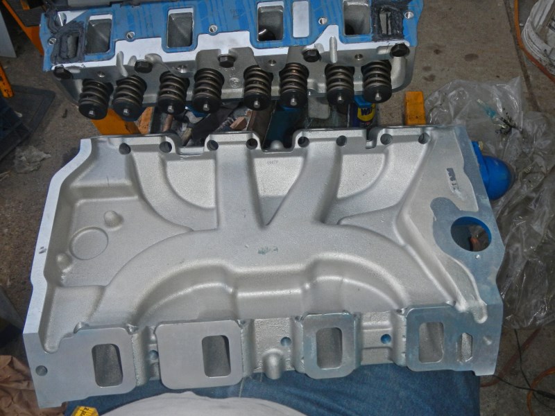
Many restorers omit the valley baffle plate. I see no harm
in keeping it. Notice the intake manifold gaskets are in
place with Permatex black only around the water ports (on both
sides of the gasket.
 #32
#32
The intake manifold eliminates exhaust crossover, and sends the
hot exhaust out each exhaust manifold.
Sealing this manifold has caused many restorers fits because as
the bolts are tightened, the whole manifold slides down under
the bolt heads. Sometimes this causes the gasket to
'squirm' and leak at the coolant ports. Therefore, I take
two precautions: I don't put gaskets on the front or rear
of the block (where the intake manifold mates). Instead, I
fill the area with Permatex after the intake has settled all the
way down. AND, after the intake manifold bolts are
slightly tight, I then torque the head bolts.
 #33
#33
This is the earliest opportunity to install pushrods because
they go through the intake manifold. The problem with this
is, we don't know what length the pushrods shoud be since the
lifters are a lot higher than stock lifters, the cam is
different, the cam timing is different, etc., etc., ... We
need to install rocker arm shafts, measure for pushrod length
and check valve-to-piston clearance. Notice I have one
pushrod sticking up for #5 cylinder.
 #34
#34
The intake manifold doesn't come with the 5/8" diameter water
pump bypass nipple. I cut this one and pounded it in,
leaving 1-1/4" sticking out for the 5/8" rubber water pump hose.
Also notice, the timing chain cover is installed along with the
fuel pump and oil filter adapter.
 #35
#35
These fittings were swapped from the old manifold. The
small brass fitting is the temp gauge sending unit. The
ell is the supply for the heater. The open threaded hole
is for vacuum (power brake booster, ignition advance and PCV
valve).
 #36
#36
Here is the new fuel filter.
Top of Page
CLICK HERE
to return to Home Page