
![]()

|
|
|---|
Awhile back I bought a 'dead' gauge cluster for our '59 Galaxie. I really wanted the chrome surround bezel, but it came with the gauges and speedometer. I paid $15 for it and sure enough, you get what you pay for. The speedometer was frozen, none of the gauges actually worked and all the dials looked like they were buried for decades. The good news is I had the pot metal bezel re-chromed, I'm using it and it looks beautiful. I never thought my purchase might be worth much more as a learning tool for Squarebird gauges, but it is...
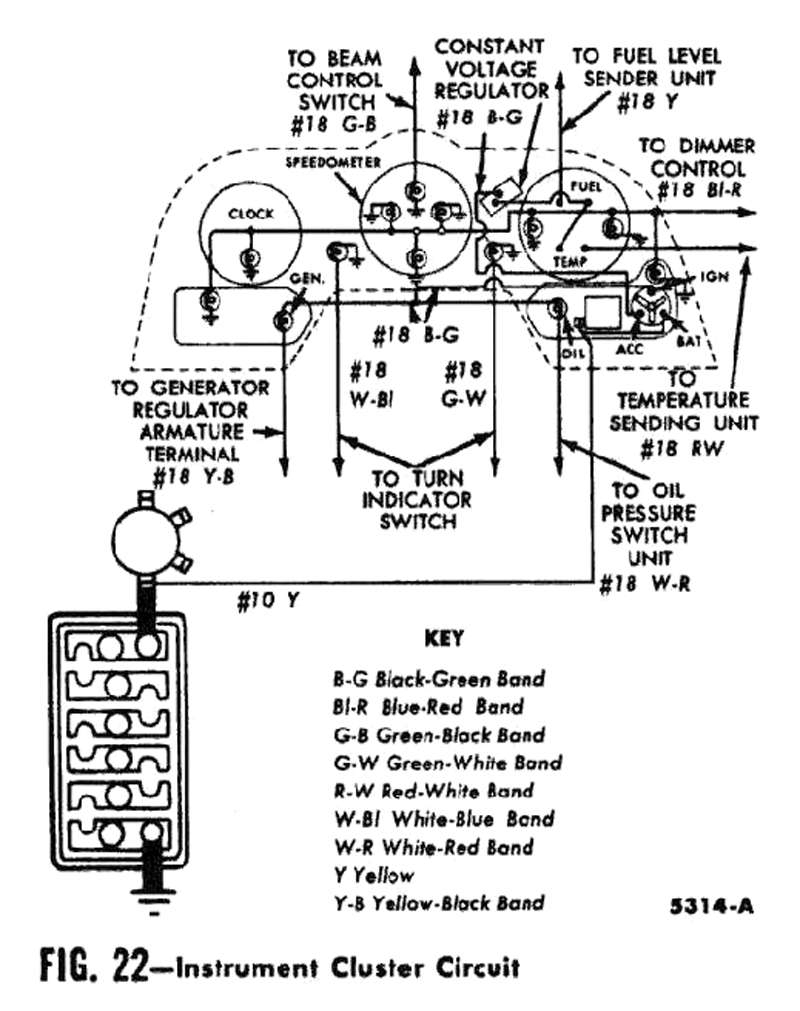
Our gauges are fed with pulsating 12 volt current from the Constant Voltage Regulator. Current is only allowed to pass if the Fuel Tank Sending Unit has a low resistance (or the TEMP Sending Unit has a low resistance). Both gauges are identical internally and the guts can easily be swapped.
Squarebird gauges are oriented slightly different but Ford used the same movements across all their car and truck lines. They are incredibly inexpensive to manufacture, they give a fair degree of reliability and they usually last many decades.
 #1
#1
 #2
#2
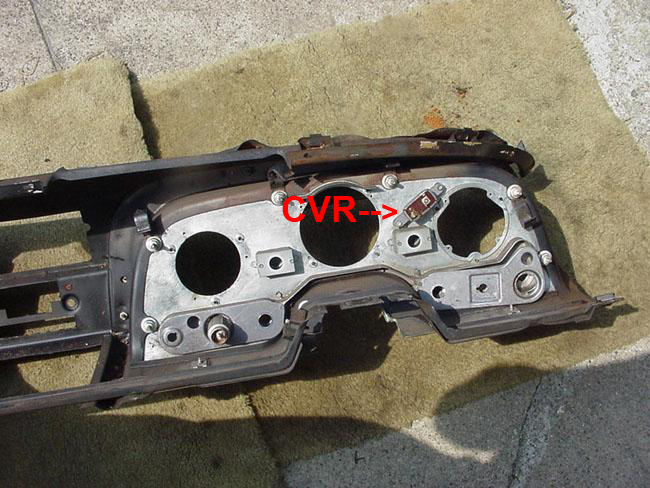
Here is the layout as seen from the back of the SB dash...
 #3
#3
The Fuel and Temp Gauges are identical in construction, which makes testing and
troubleshooting the same for both.
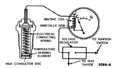
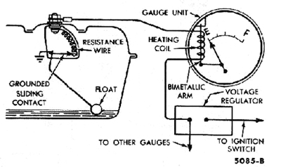 The gauges use a bi-metal strip, but no contacts. The circuit starts with 12 volts, the CVR averages 6v, & the Sending Unit varies current to GND (B-). |
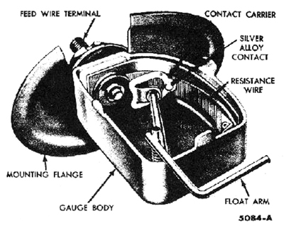 This is a Fuel Tank Sending Unit. When the tank is full, resistance is 0 & the Fuel Gauge goes to the max (F). |
Temp Gauge:
 #6
#6
Temp Gauge operation is identical to the Fuel Gauge.
 #7
#7
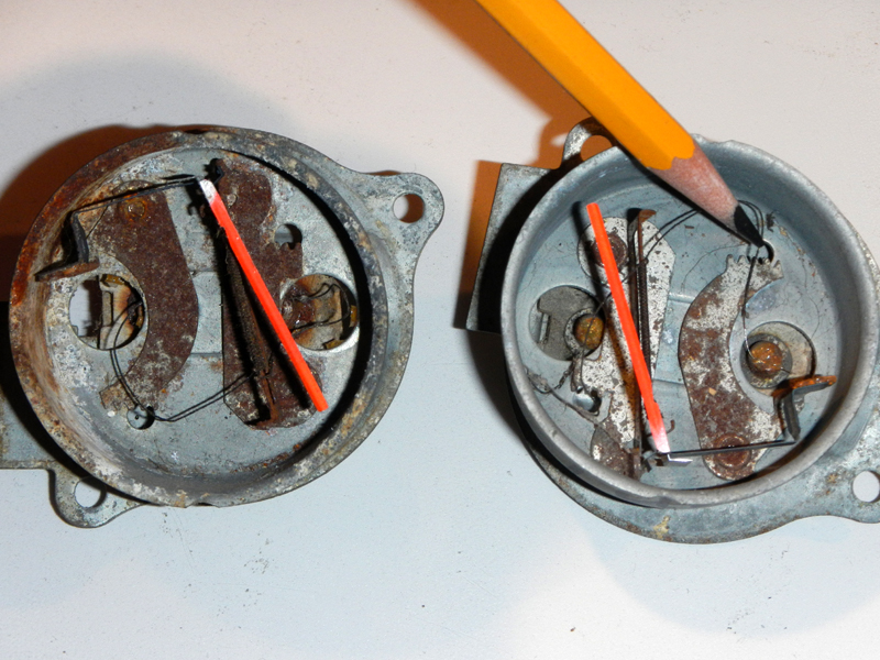
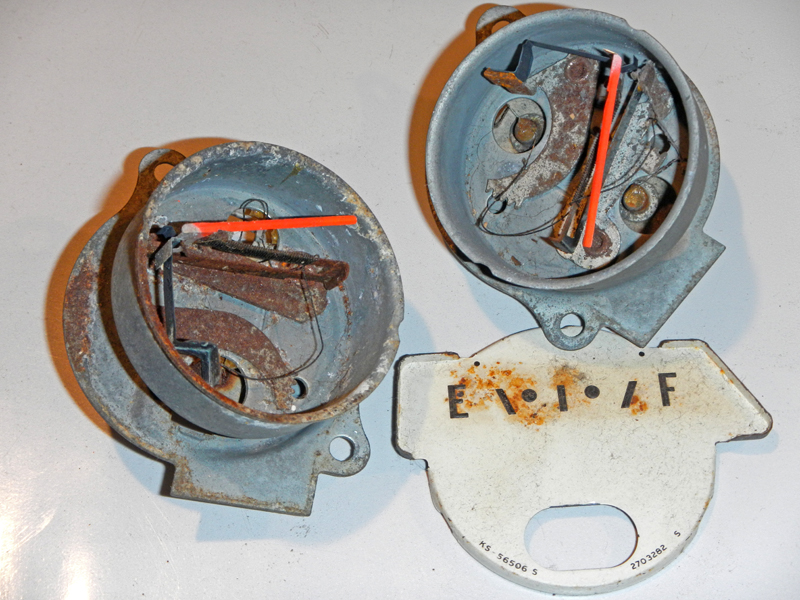
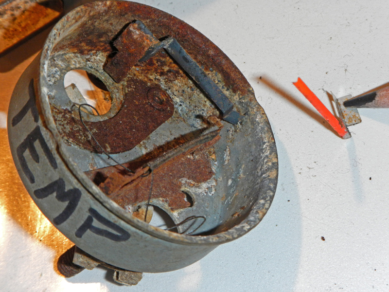
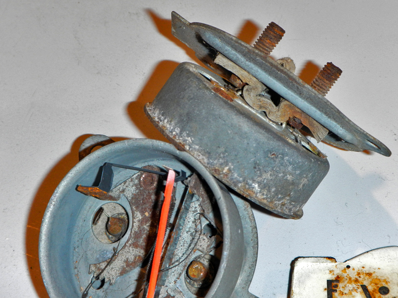
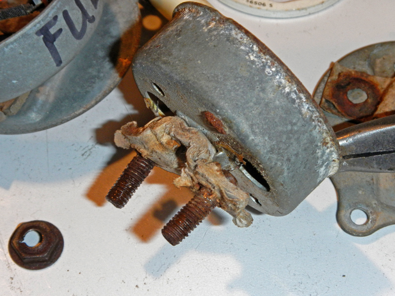
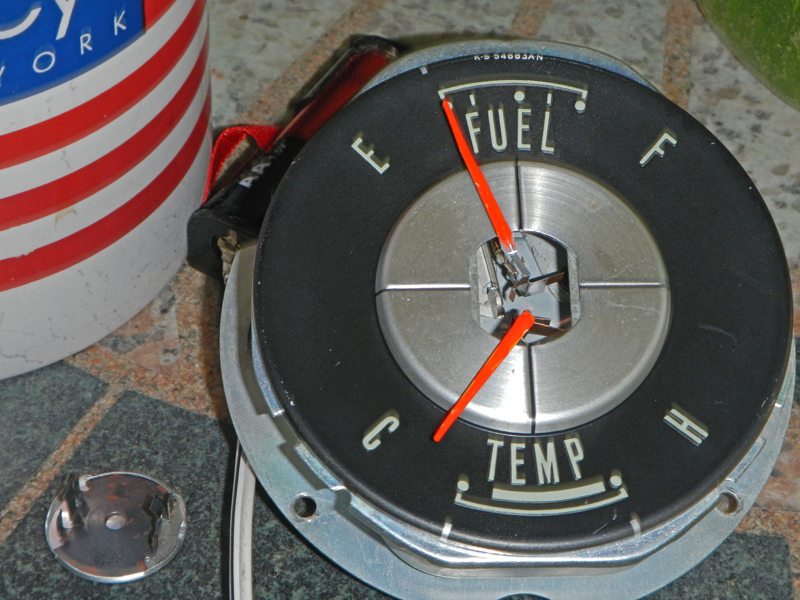
These are the trashed gauges for a 1959 GALAXIE. One
is a Fuel Gauge and the other is the Temp Gauge. Let's get passed the rust
and notice a few things about these gauges. The fine ni-chrome wire wraps
around a bi-metal strip. Ni-chrome wire is made of nickel and chrome and
it is a terrible conductor with high resistance. When small amounts of
current pass through, the wire heats the bi-metal strip. Bi-metal, as the
name implies, is a sandwich of two dissimilar metals that expand at different
rates when heated. This causes the metal to bend when hot. When a
pointer is attached, the bi-metal strip pushes it sideways in proportion to the
heat. There is a leaf spring that helps return the pointer to the 'at
rest' position when the bi-metal cools. That leaf spring is at the bottom
of the needle, pulling it down. So, now we have two forces working on the
pointer needle (one sideways and one down).
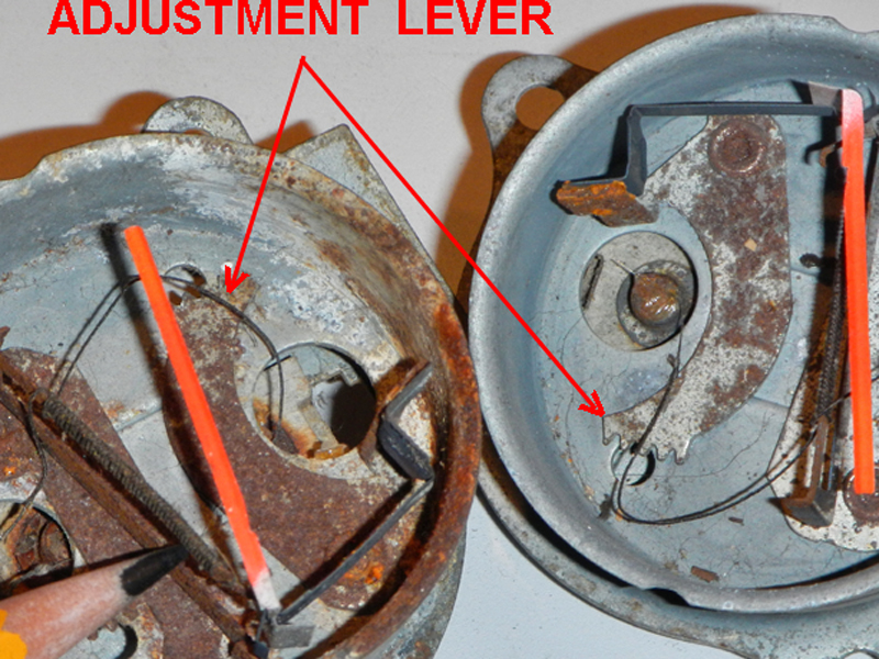
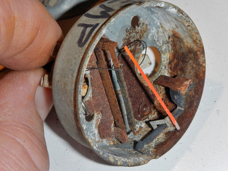
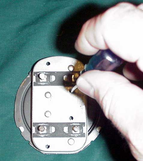
The leaf spring and the bi-metal strip are both on separate adjustment arms that
pivot. Each arm has adjustment teeth, accessible through holes in the back
or from the front (behind the dial).
Because the needles are activated by heat (not magnetism), it makes NO
difference which way the power wires are connected to the rear posts.
 #8
#8
 #9
#9
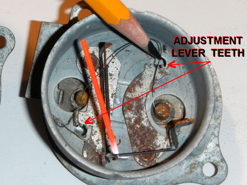
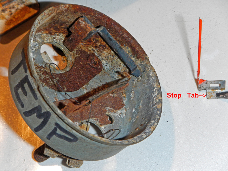
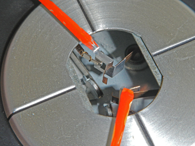
Notice there are TWO sets of teeth, one on each pivot arm. The bottom set
is just to the left of the needle base. To get any serious adjustment, the
needle needs to be tweaked at the square hole. The bi-metal arm (on the
left) adjusts the needle for sideways deflection. The arm on the right
pulls down harder for sensitivity. The tab on the needle is the stop.
 #10
#10
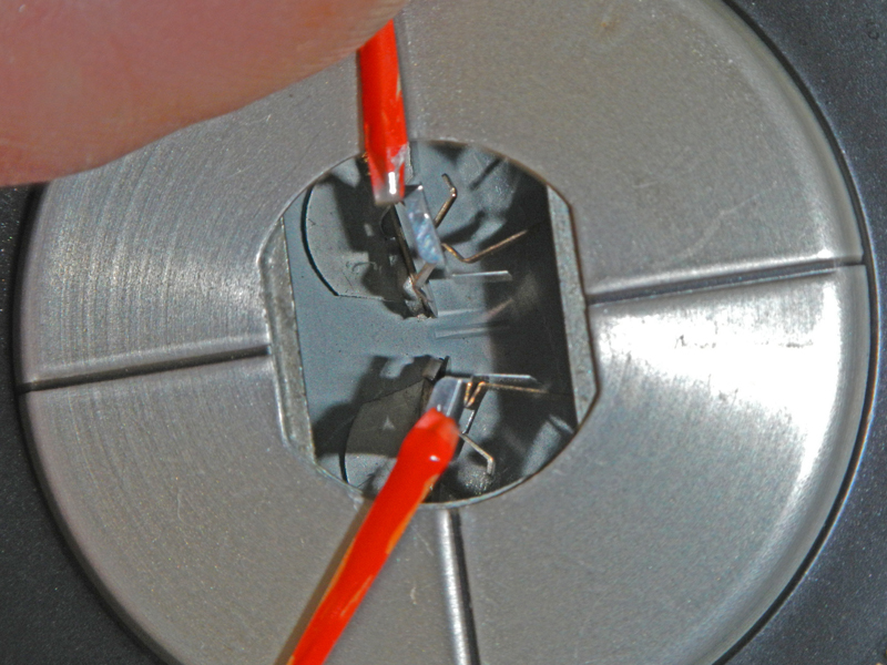
BTW, the dial slides off after I gently lift the needle. The needle does
not bend, but simply rotates in the square.
 #11
#11
Here I detached the needle from the bi-metal strip and slid it back on the leaf
spring. Now, it is easy to see how the needle hooks on to both ends using
the square hole.
 #12
#12
I will go over this a few times. I have removed the needle to show all the
bends.
 #13
#13
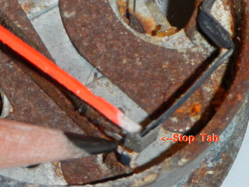
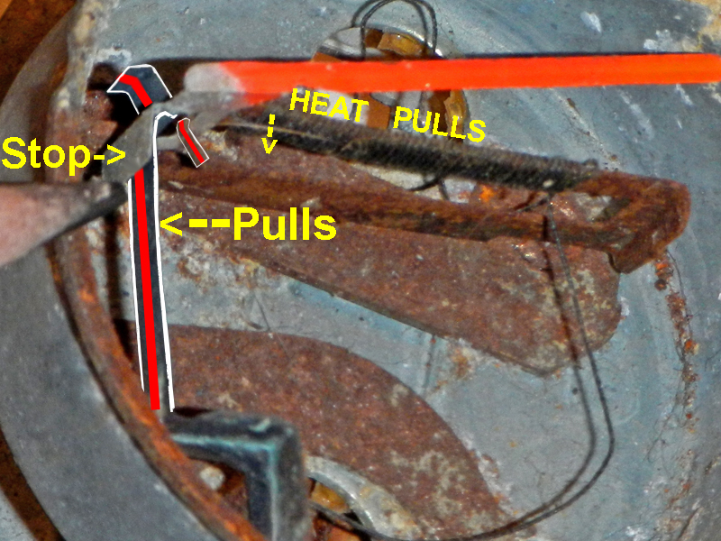
The portion my pencil is touching is a stop tab. When it is 'at rest' on
the leaf spring the needle cannot move down any more. If the needle does
not return all the way, something is between the 'stop tab' and bottom leaf
spring, possibly a spider's web or a piece of something. If all is clear,
bending the Stop Tab adjusts the needle's 'at rest' position.
 #14
#14
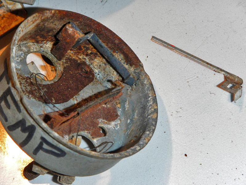
The needle is nothing special, just a piece of very light stamped aluminum.
 #15
#15
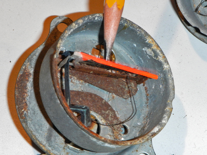
I am using a pencil to hold the stop tab down on the table. That's why the
needle is pointed straight up.
 #16
#16
With the pointer back on and when the pointer is 'home', the stop tab claps
against the leaf spring. Other gauges might use a peg, this is just
another way to positive stop.
 #17
#17
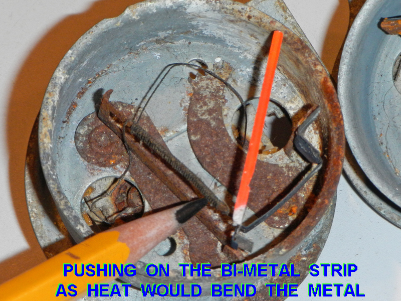
I am pushing hard enough to make the needle deflect to full scale. Notice
the action at the bottom of the needle.
 #18
#18
Now the needle is back home and stopped, 'at rest'.
 #19
#19
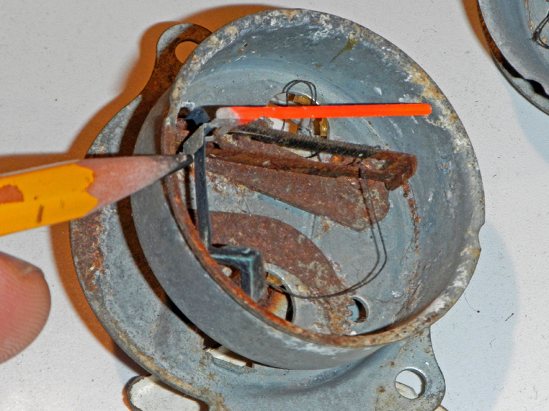
Here are the forces at work... The long strip on the left is the 'return'
leaf spring. The horizontal piece (wrapped with wire) is the bi-metal
strip. There are no fancy bearings and nothing is very technical, just
plain mechanical and heat forces working together.
 #20
#20
I am giving a light push on the bi-metal strip. The needle deflects a
little.
 #21
#21
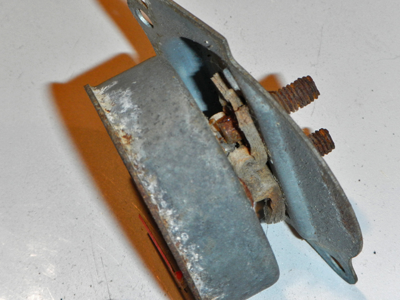
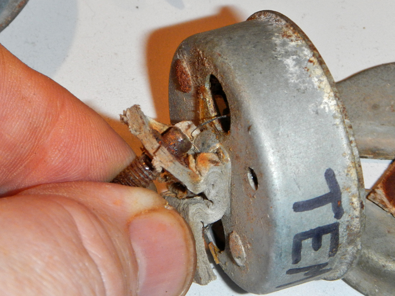
For the last part, I unscrewed the speed nuts on the back to expose the rear
posts. I do NOT suggest you do this unless you are rebuilding or replacing
the gauge. The paper is old and delicate. Those fine ni-chrome wires
are spot welded to the steel screw ends.
 #22
#22
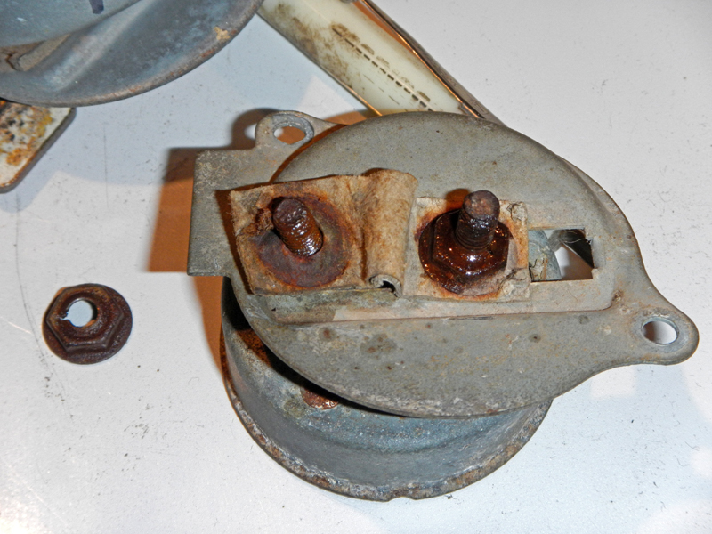
This crappy paper is on both sides of the back plate. The meter can
squeezes the cardboard just to keep it there when the bolts are removed.
They puckered the paper to allow sideways adjustment. Electrically, the
case is insulated from power by all this cardboard sandwich.
 #23
#23
Even though the nuts are thin sheet metal stampings, they came off hard. I
used lots of penetrating oil.
 #24
#24
 #25
#25
 #26
#26
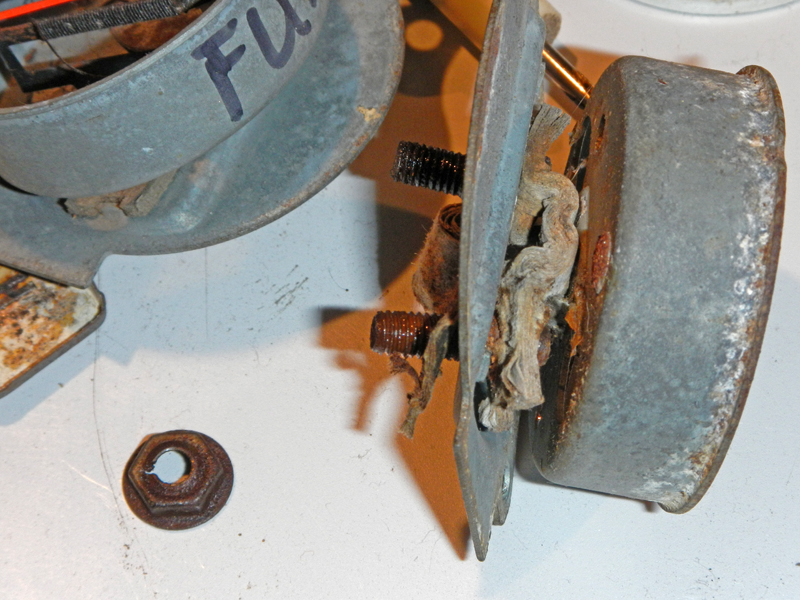
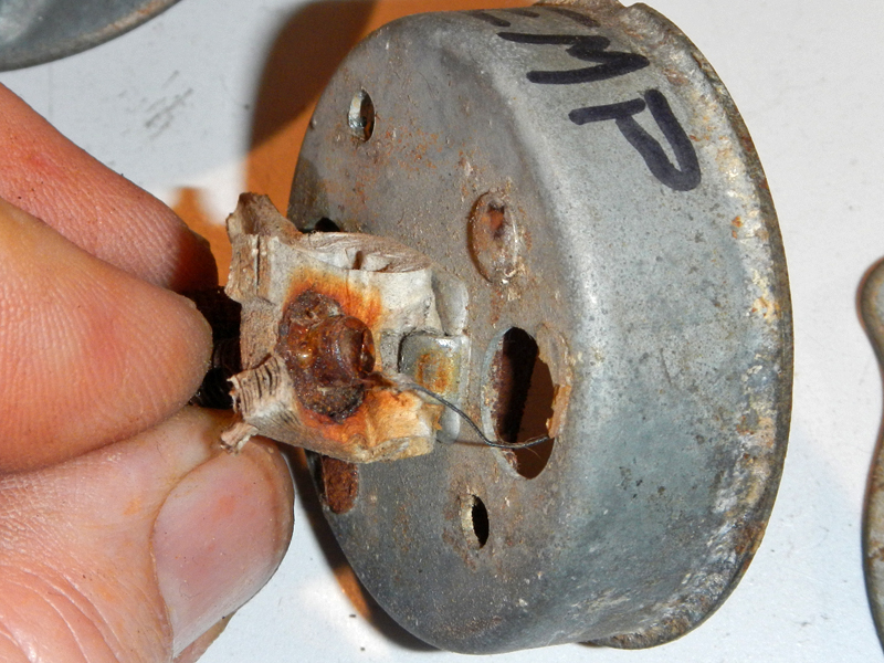
Down and dirty, it's simply two steel studs attached to the paper. They
welded the fine ni-chrome wire to the end.
 #27
#27
As I pull back the stud, notice the cardboard is pinched between two tabs.
It was great to have scrap gauges to learn how Ford gauges work, now on to
Squarebird Gauges:
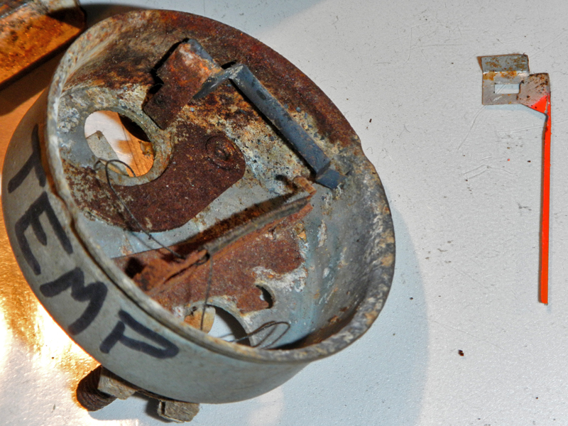
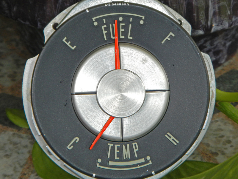
Leonard Wheeler had a problem with his FUEL
gauge; it wouldn't rest at "E". It stopped at 1/4 tank. Using what I
learned from the scrap gauges, fixing Leonard's was a snap. The only thing
I removed was the center 'button'. It simply pulls straight up and off.
All the internals are identical to the above gauges.
 #28
#28
 #29
#29
The 'center button' is removed and laying in the bottom
left hand corner of the pic. Now the internals are exposed.
 #30
#30
The top needle is the FUEL gauge. The 'stop tab' on the bottom is at the
correct 'at rest' position.
 #31
#31
Here I am pushing the needle off of the stop tab so I can see the separation
more clearly.
 #32
#32
And finally, I applied six volts to the back posts to watch this gauge rest at
"E". Here, it's on the way down.
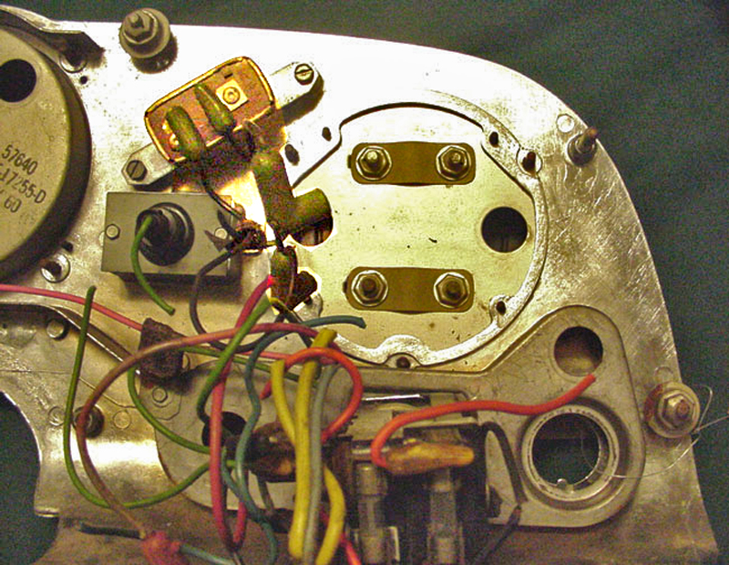
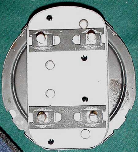
Alexander posted a few pictures of the back of Squarebird gauges for
adjustment purposes:
 #33
#33
Four access holes expose the adjustment teeth. Notice that Squarebird
gauges have the exact same setup, using two arms that pivot on their rivets with
two holes for adjusting the arms. The only difference is, these two gauges
are mounted on one back plate.
 #34
#34
![]() #35
#35
 #36
#36
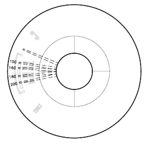
I question how accurate this is because true readings depend on a number of
factors that change;
ambient gauge temp, OEM CVR voltage & frequency (solid state CVRs deliver steady
voltage and they don't have a frequency). So, a cold Chicago morning will
produce a lower gauge reading until the dash heats up. That's why you may
feel engine heat before the needle starts moving.
The same holds true for the Fuel Gauge. A cold gauge may report less gas than you actually have in your tank.
- simplyconnected
