 1.
1.
PISTON-TO-VALVE TIMING
CLICK HERE
to return to Home Page
What could possibly be more important than the
clearance between pistons and valves in any engine? OEM engine
setups have been done at the factory. If ANY dimension has changed
between the piston and valve train, clearance must be measured.
In this case, the block is decked, pistons are a new height, the head
gasket is different, the heads are aftermarket Edelbrocks, the cam is a
new hydraulic roller with Morel lifters that include a 1/2" roller and
shorter pushrods, I'm not using oil deflector pans under the rocker arm
shaft stands. These valves are much larger than OEM.
All these
changes make simple calculations impossible by adding the components. Clearance must be
physically measured.
1.
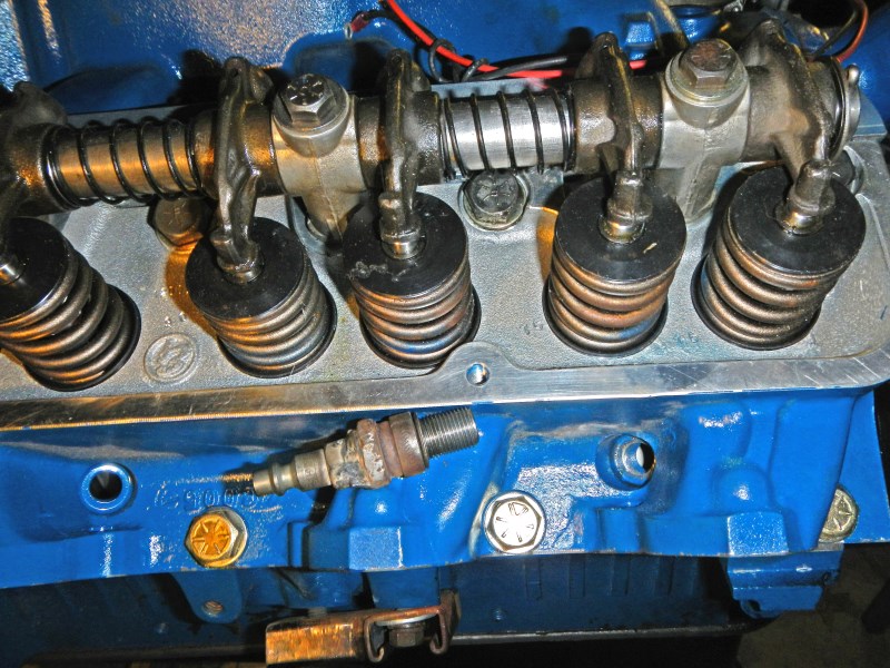
I start by using a home-made tool, a gutted
spark plug with an air hose fitting welded to the top. The
fully assembled head is bolted with a new head gasket, torqued to spec's.
100-psi of compressed air will hold the valves closed while I remove
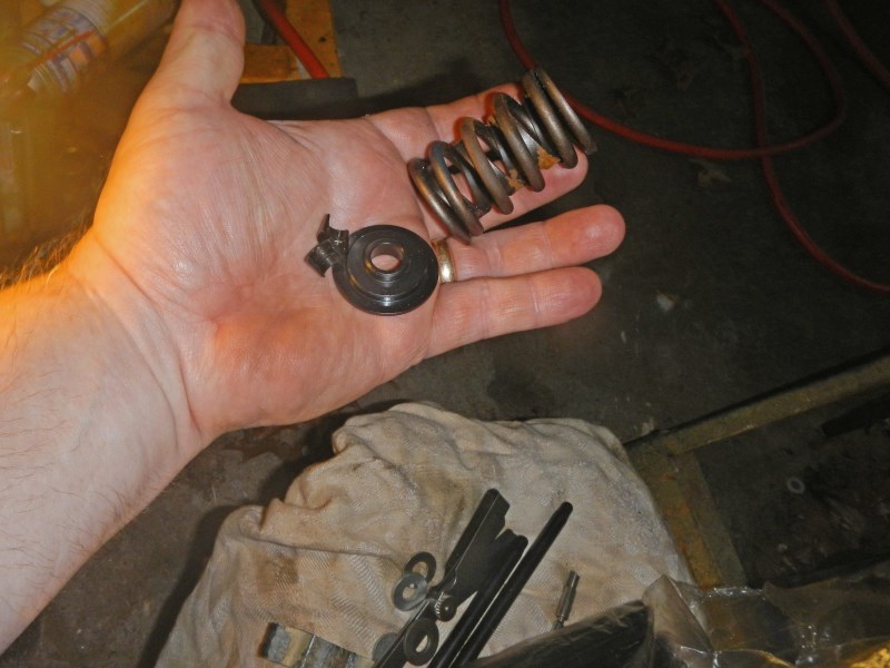
two springs. Some folks use a weak (test) spring on the
valves. I use no springs. The idea is to rotate the
crank while descending the valve by hand to feel the closest
proximity between the piston and valve, then measure the gap between
the rocker arm and valve tip with a feeler gauge.
This
is more easily done with solid lifters. I only have new
hydraulic roller lifters that are dry, so I must feel the gap with
NO PRELOAD. I don't want any mistakes so I must have a very
light touch for a true measurement.
 #2
#2
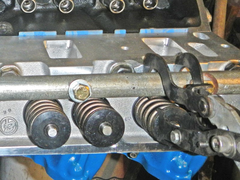
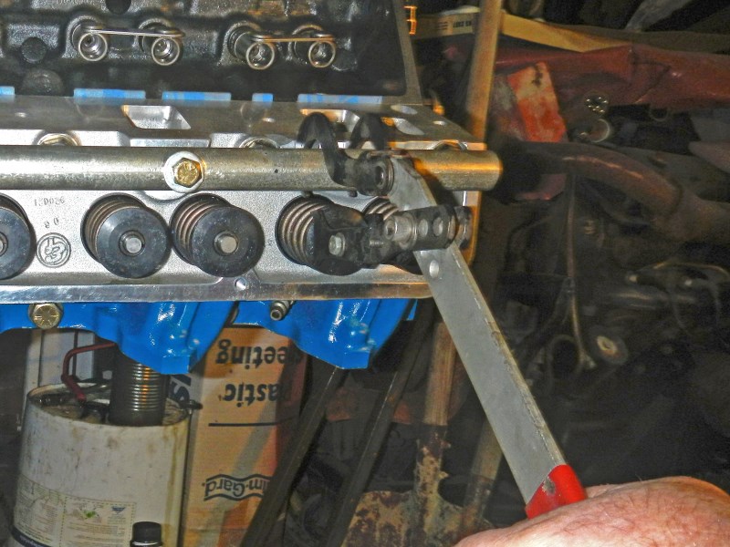
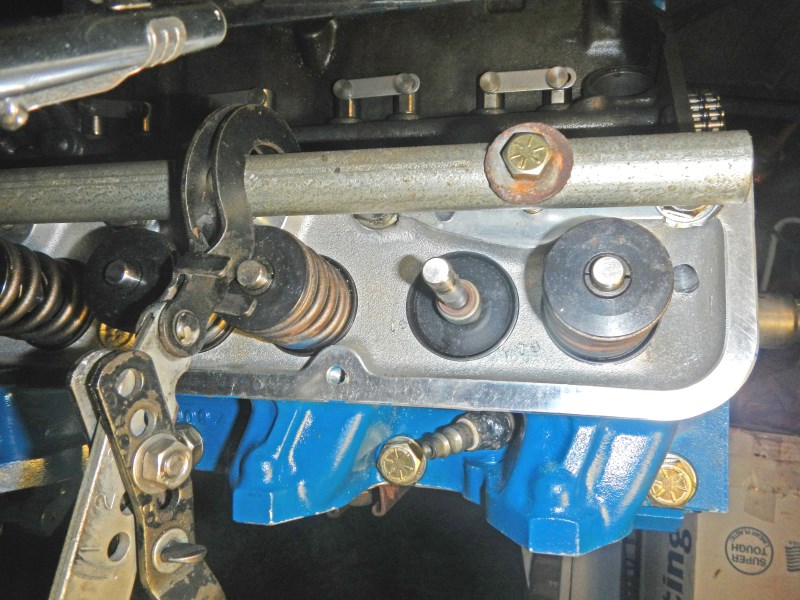
There are several different methods for
removing valves in an assembled head. Here, I used a 'lever'
type spring compressor. One end hooks around the rocker arm
shaft while the lever compresses the valve spring. Again,
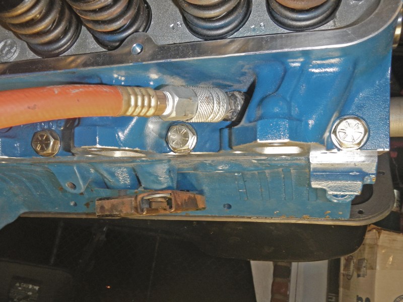
compressed air keeps the valve tightly closed. Make sure the
piston is at the bottom before connecting the hose.
Instead of
using a real rocker arm shaft, I made a temporary setup from a piece
of 3/4" EMT (conduit).
 #3
#3
 #4
#4
 #5
#5
 #6
#6
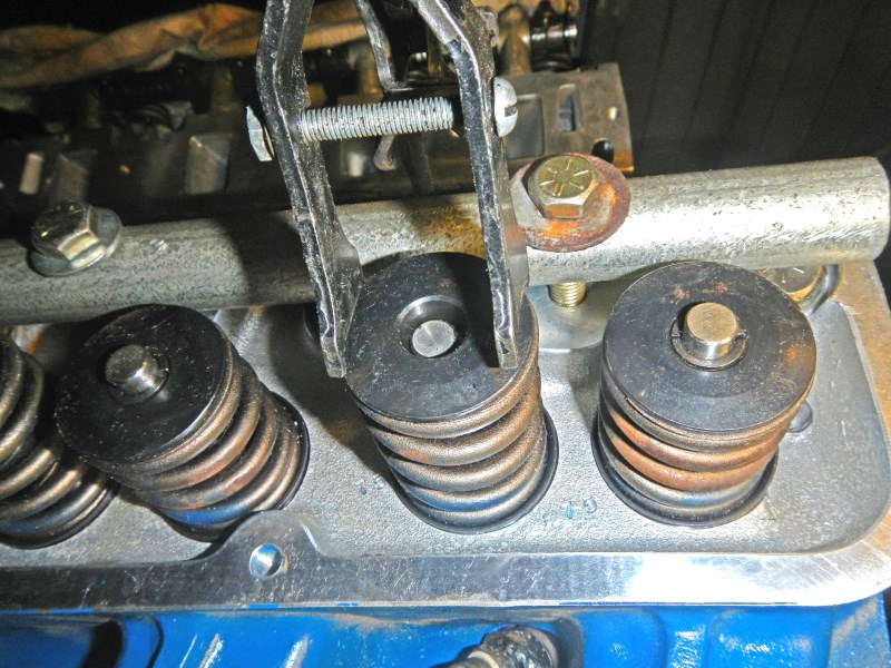
With 100 PSI of air still connected, I compress the spring and pull the keepers out.
 #7
#7
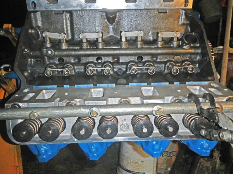
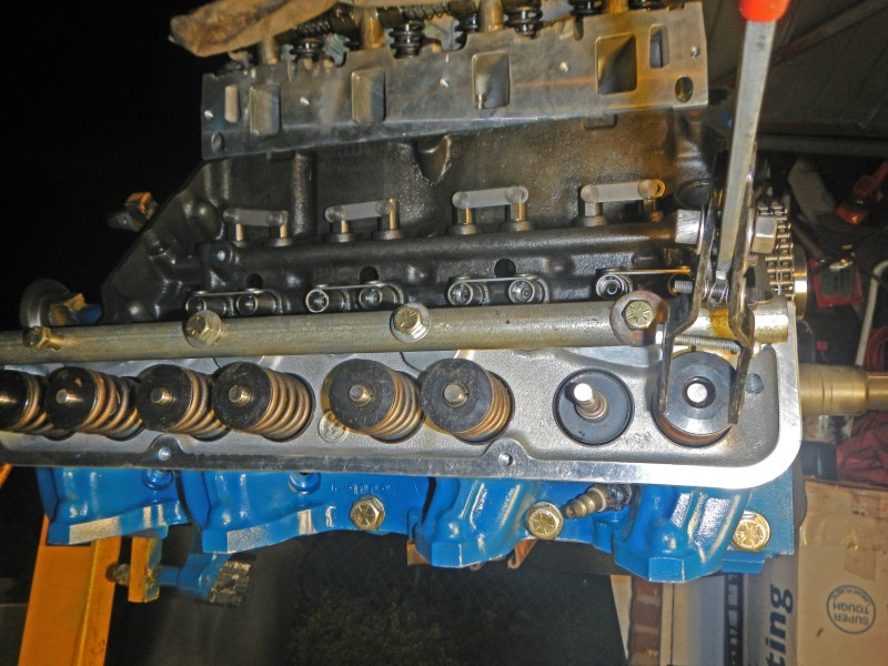
I put a wire around the valve stems to hold them up, then I release the air hose and mount the rocker arm shaft and insert two pushrods.
 #8
#8
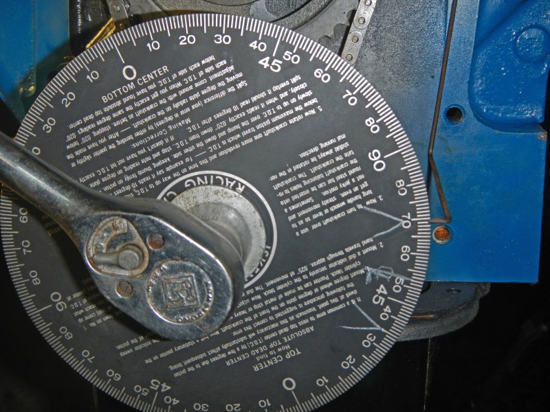
Here, I am checking #6 lifters to verify the cam and crank are at TDC.
My valve clearance is better than .1", which is very good.
Time to reassemble the valve springs and mount the intake manifold
but first, a slight adjustment must be done to the baffle plate...
 #9
#9
It's all clean and ready to go except the tall roller lifter next to
the distributor hit it. I simply bent the corner up with a
pair of pliers. (See Intake Manifold Install)

 #10
#10
T
#11
#12
Y
#13
A
#14
#15
#16
I.
#17
A
 #18
#18
#19
N
#20
O
#21
T
#22
L
#23
P.
#24
I.
#24
1
 #26
#26
R
Top of
Page
CLICK HERE
to return to Home Page