The Ford FE series engines used two distinctly different methods of oiling that are well documented. For this site, I discuss the 1973 390 FE/TE method. The Ford Y-Block had a terrible oiling system. The FE is the 'next generation' Y-Block with vast improvements. Production FE engines benefit greatly from hand-built oil modifications, discussed here.
 #1
#1
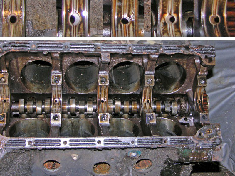
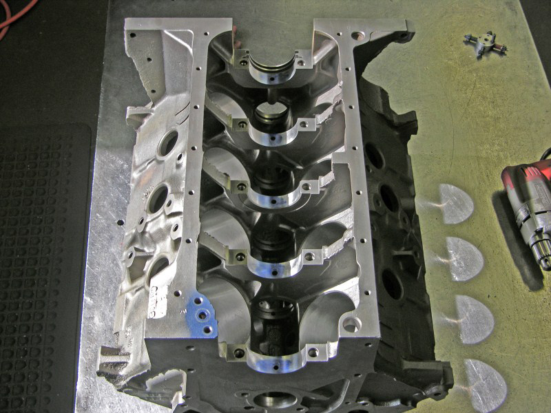
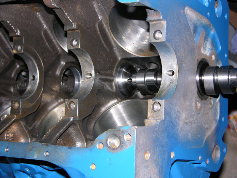
'Engine Teardown' often shows the real story of what's going on.
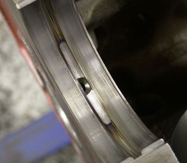
Notice how misaligned the oil holes are. I enlarged the
bearings and displayed them on the top. I had just pulled the
crank out and as you can see, the bearing shell halves are perfectly
centered.
 #2
#2
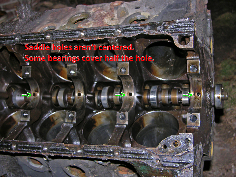
This is clearly an engineering and machining mistake from Dearborn Engine Plant.
 #3
#3
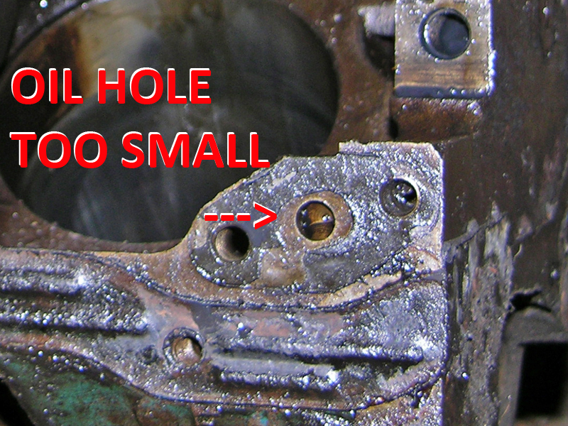
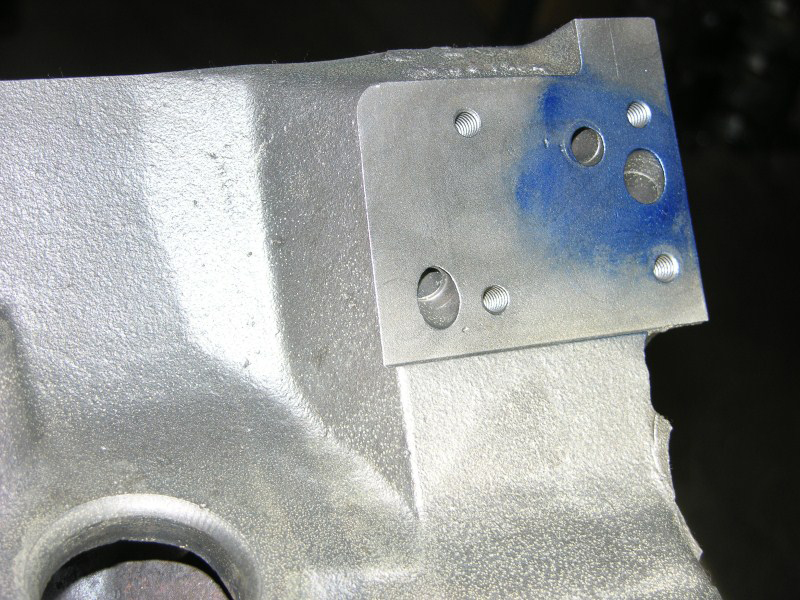
This Oil Pump hole is restricted by its size. The gasket shows plenty of room for a much larger 7/16" hole.
 #4
#4
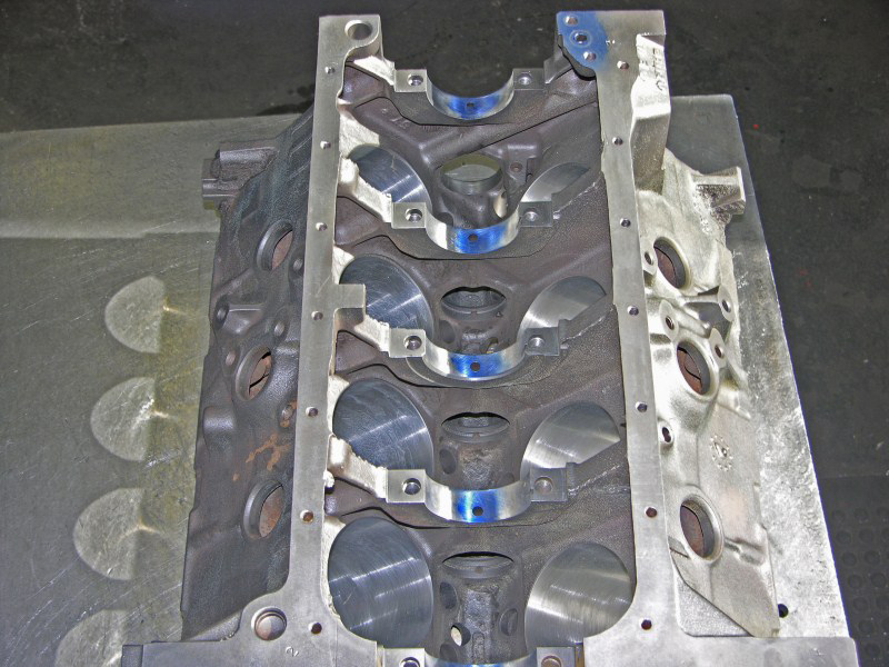
After boring and decking the block, I used blue layout ink and a scriber to trace new bearing and gasket
holes. This leaves a 'guide' for opening the holes.
I used a simple hand drill with a carbide burr to remove iron and smooth the holes so they offer unrestricted oil flow.
 #5
#5
 #6
#6
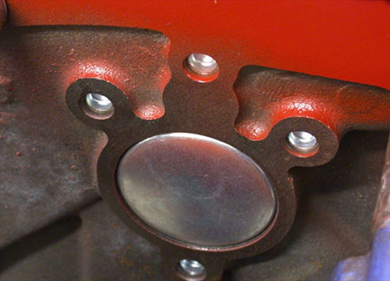
These are the Oil Filter in and out holes, fed from the Oil Pump.
The filter adapter bolts onto this surface.
 #7
#7
Here is the Oil Pump hole after modification.
 #8
#8
This is #1 main bearing saddle. Notice that I chased all threads with a good tap. I am meticulous about removing all
chips, using a magnet then high water pressure. You may see some 'flash rust' as a result. I remove that later.
 #9
#9
All the main saddles are done.
 #10
#10
This view shows how the oil hole looks with a bearing. It's quite an improvement over the 50%-covered original location.
 #11
#11
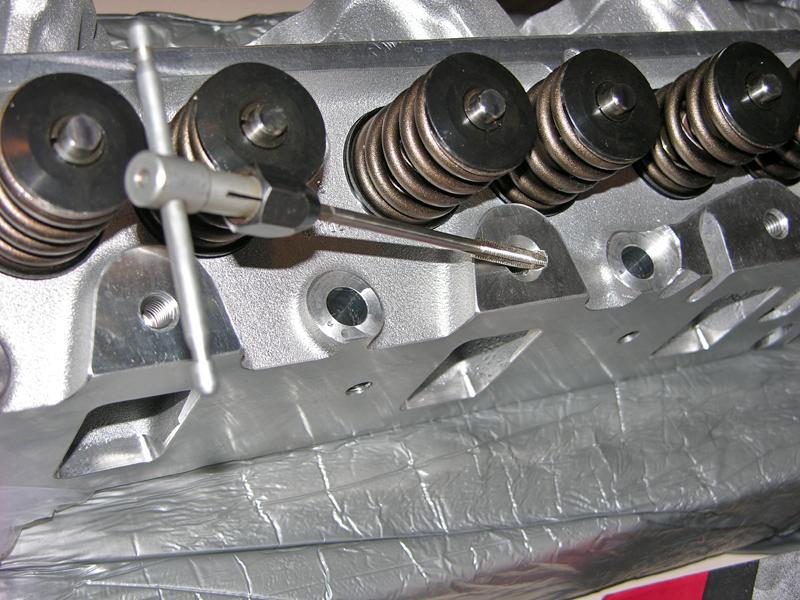
Next, I restrict the Rocker Shafts in the Heads. If left unrestricted, oil pressure drops to about 5-psi at idle, and at
running speeds the valve covers tend to fill with an extra quart of oil on top of the heads.
 #12
#12
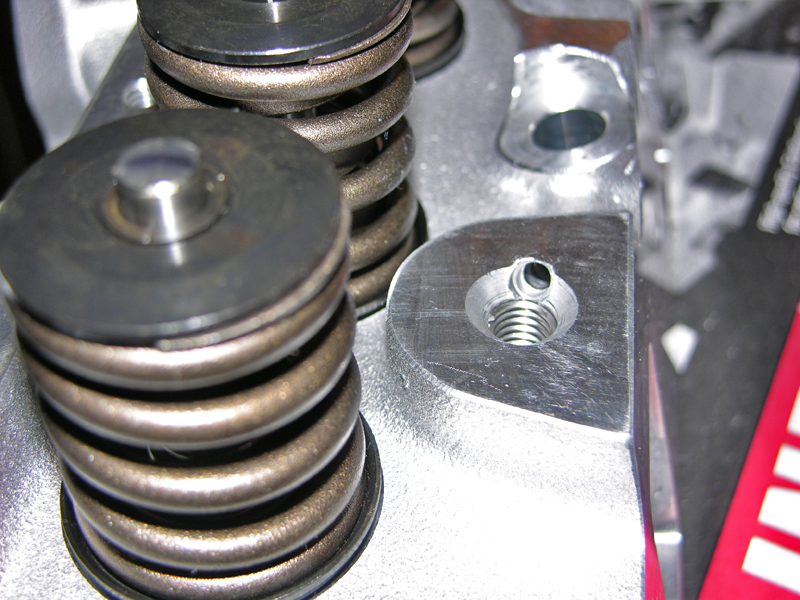
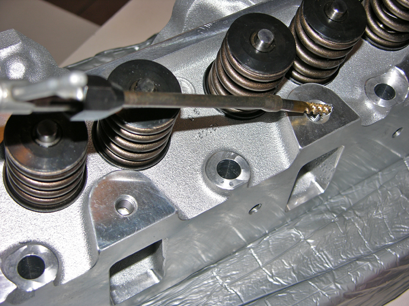
These are new, CNC machined, Edelbrock Performer RPM aluminum heads. In my opinion they are the best bolt-on component your FE could have. Aluminum is very soft and easy to mess up when tapping by hand.
I use two 1/4"-20 taps; the first is a very long taper that controls
straightness, the second is a spiral tap which curls the chip out (not in).
 #13
#13
1/4"-20 spiral tap.
 #14
#14
Both heads are tapped.
 #15
#15
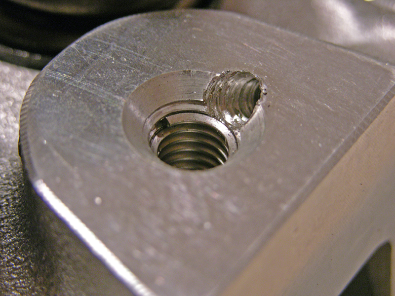
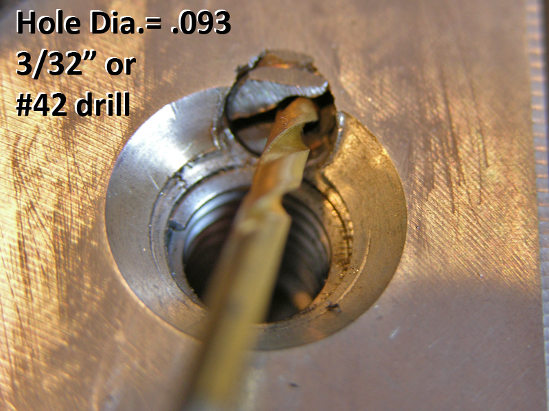
I fabricated a removable plug from a soft steel bolt. I cut the screwdriver slot with a hacksaw then drilled my oil hole
afterward. Some guys use a brass carb jet because it has a head. I wanted mine recessed with clearance below the
stanchion bolt chamfer.
 #16
#16
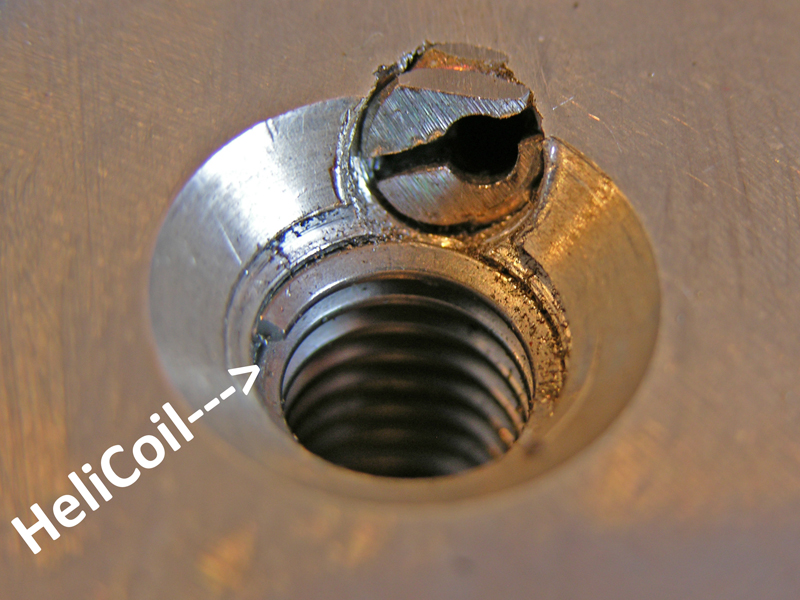
Minor chip cleanup from filing the top flat and it's done.
Edelbrock Performer RPM aluminum heads scream, 'quality'. They use stainless steel thread inserts, have 5/8" of meat on the bottom (in case they are to be shaved for smaller combustion chambers and higher compression), stainless valves, new springs, hardened valve seats, bronze valve guides and Viton valve stem seals. For this build, we are keeping them stock. I have a set of these on my 351W for over 100k-miles. They still work and look great.
 #17
#17
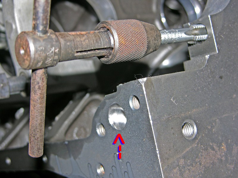
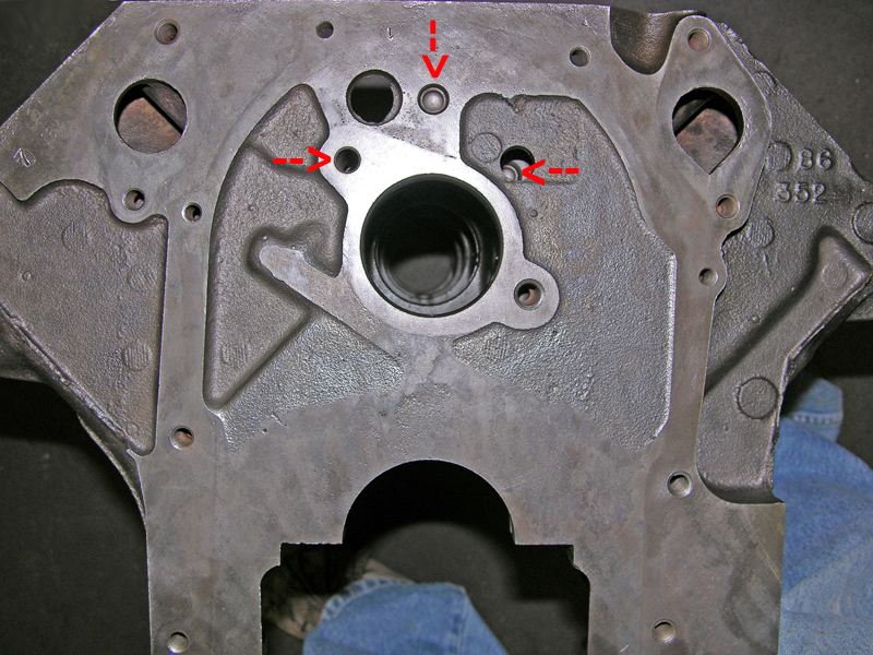
FEs have two holes that run the entire length of the block. They feed the lifters. This is the front of the block, where the
Thrust Plate bolts on. The left arrow points to the top Thrust Plate bolt hole. That bolt also plugs the oil hole. The
right arrow shows a 'hidden' plug behind the distributor hole.
 #18
#18
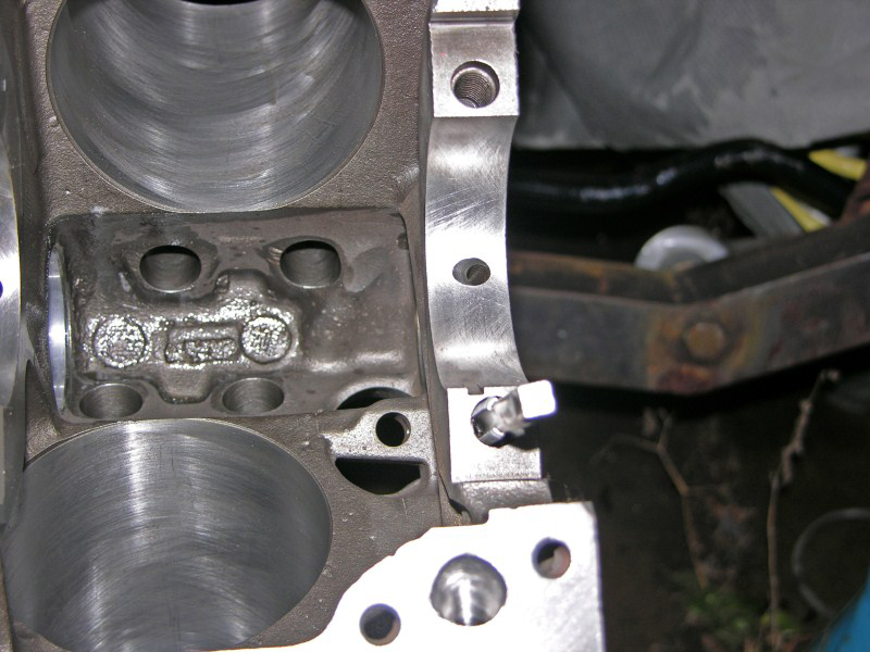
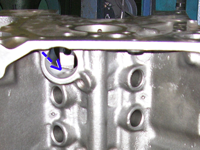
The blue arrow shows where the plug goes inside the distributor hole. If you follow the holes straight down, it's easy to see
these are feeding the left and right lifter bosses.
 #19
#19
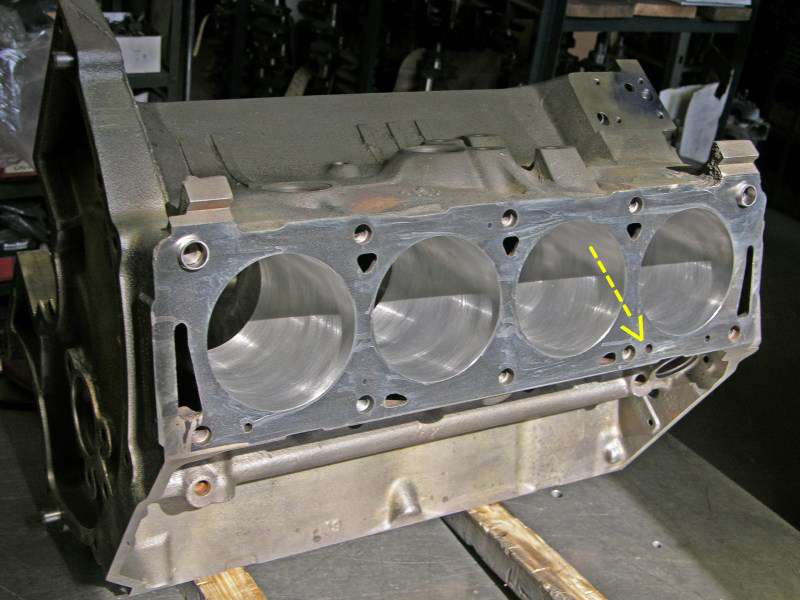
Here's a picture of the rear of the block. All plugs are out and light shines straight through the oil holes. It's
important that these holes get cleaned and brushed before re-assembly.
 #20
#20
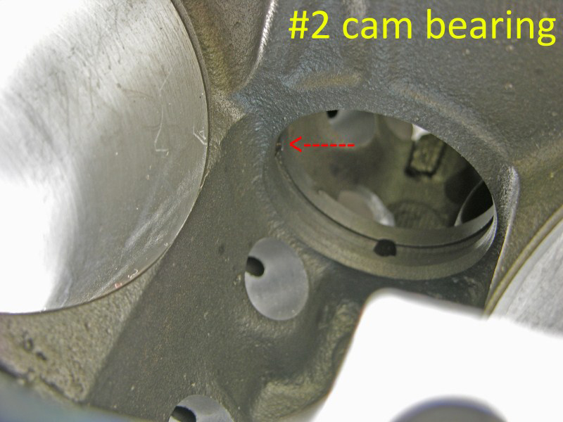
#2 and #4 cam bearings feed oil to the Rocker Shafts. These two journals have a deep groove machined in the middle,
under the cam bearing. If these two cam bearings are not inserted properly, the bearing could starve the Rocker Shafts of
oil. #2 Cam Bearing feeds the left head and #4 feeds the right head.
(BTW, you can see the oil through-holes that feed the Lifters.)
 #21
#21
This is where the oil comes through to feed the LH Rocker Shaft. To check for proper flow, simply blow into this hole and feel for
wind at the cam bearing. If there is a restriction NOW is the time to correct it, before the cam is inserted.
 #22
#22
This is the rear of the engine at the Cam Plug. This is the proper orientation for either FE or Y-Block Cam Plug.
 #23
#23
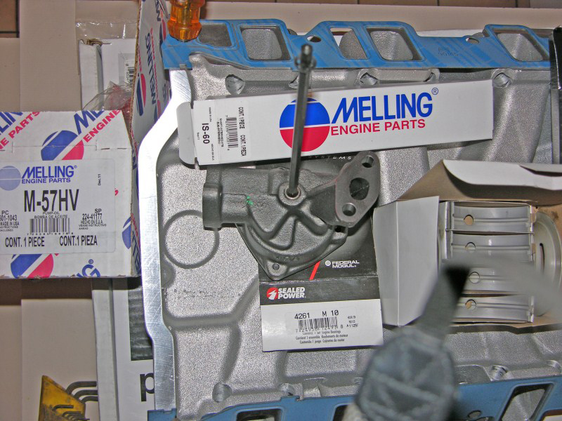
For good oil pressure at idle and throughout the rpm range, this High Volume Melling Oil Pump (M-57HV) and
Intermediate Drive Shaft (IS-60) are a 'must have' along with
these oil modifications.
FE engines
are very different, and inexperienced mechanics often omit important internal oil plugs resulting in no oil pressure.
FE engines haven't been produced in many years. Most of the experienced FE mechanics have retired.
Consequently, new mechanics rarely see them and very few have worked on them.
The same holds true with Cruise-O-Matic and C-6 transmissions.