
1960 SQUAREBIRDS POWER WINDOW & SEAT MOTORS
BY: 60 T-Bird (Martin Burs), Tbird1044 (Nyles Beuchel), gaffney1951 (Mike Gaffney) & Simplyconnected

Power Window & Seat Motors from 1959 and 1960 look the same from
the outside. Pre 1960 motors have the commutator and brush assembly at the
shaft end. '60 and later motors have the commutator and brushes at the rear or
'bell'
end. Before cracking one open,
extreme care must be exercised or your brush holders may be damaged by simply
taking it apart. Even though you cannot tell which motor you have, this can be avoided. Please read carefully
and follow Martin's pictures:
|
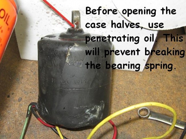
Picture #1
The two long mounting screws were removed for easy wheel access. Before
attempting disassembly, BE SURE there are no dents or raised metal (dings) on
the motor shaft. A shaft ding will hang up on the bearing, causing unnecessary
damage and a mad scramble for specialty non-conductive, heat resistant parts made of unobtanium. Use a
fine file or Diemaker's stone and go over the shaft surface. Any
imperfections will show up immediately. File or stone them smooth.
|
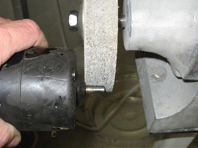
Picture #2
This is a (3M) ScotchBrite wheel,
not a grinding stone!! The purpose is to remove paint, rust, and
scale, not dents or dings.
|
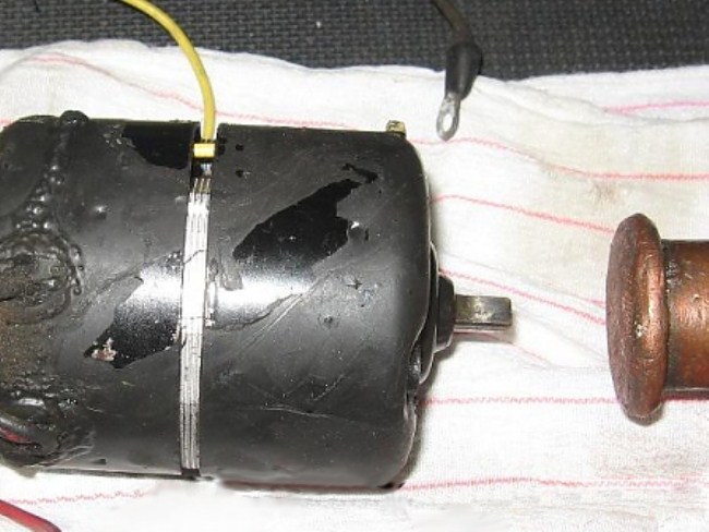
Picture #3
File the set screw marks so they aren't raised.
I'm reluctant to show a hammer here.
It is important to hold the motor by the housing's FRONT HALF and gently tap the
motor shaft. The shaft should slide off the bearing easily. If you feel resistance and the front shell doesn't remove
easily, DO NOT FORCE IT. Look for an obstruction on the motor shaft.
Continue smoothing until the shaft slides off the bearing easily.
Nyles has another important caution. "One thing that really got
me is that, even light tapping on the motor shaft, can move the shaft inside
the armature. Then when you put it back together, the rotor will bind. A
little tapping will get it back into location, but that is where it gets a
little tricky, since you have no measurement to go by. I finally have some
target numbers to shoot for and will check shaft location on my last motor,
before I reassemble. I always test run my motors after rebuilding."
**CLICK HERE and
scroll down to Nyles' last pictures for correct motor shaft placement drawings.
|
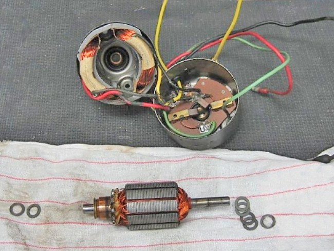
Picture #4
Here are the parts laid out. This is really an "after" picture, shown to
keep track of the washers as they help control end play and center the armature
(and brushes) inside the housing.
|
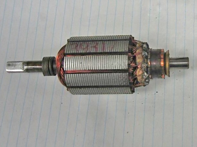
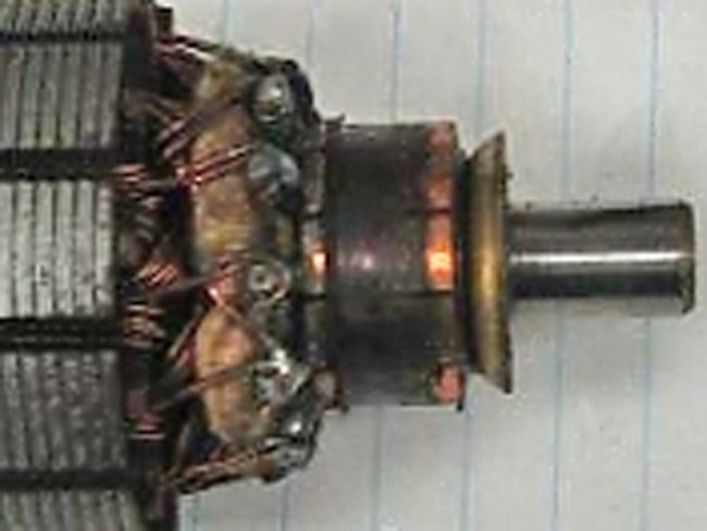
Picture #5 This is the armature before the commutator
segments are cleaned-up. This commutator shows evidence of excessive oil or
grease, but a closer inspection shows no burned, scored or tapered *segments.
Caked-on grease will stop the brushes from making contact causing the motor to
not work, BUT... there is a big difference between a thin layer of carbon and a
thick cake of crud.
* Commutator segments are made of soft copper surrounded by micarta or bakelite.
The brushes are made of carbon-impregnated bronze. This combination serves
many purposes:
The materials are heat resistant because brushes run hot from lots of
current and arcing.
Brush carbon naturally forms a lubricating surface on the copper segments that
current easily passes through, so motors should last many decades. Do
not sand this carbon film off.
|
As a LAST resort, a disfigured commutator can be 'trued' by tooling the
copper down on a lathe, but the lubricating carbon 'skin' will be gone from the
surface and the micarta will need to be undercut with a knife. Then, the
brushes should be arced to match the new commutator radius (do this by hand with
very fine sandpaper on the commutator). Further 'break-in' will sacrifice
some brush length.
|
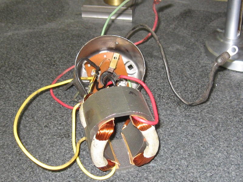
Picture #7
Nicely cleaned field co
|
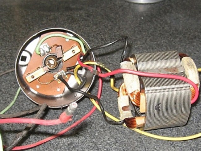
Picture #8
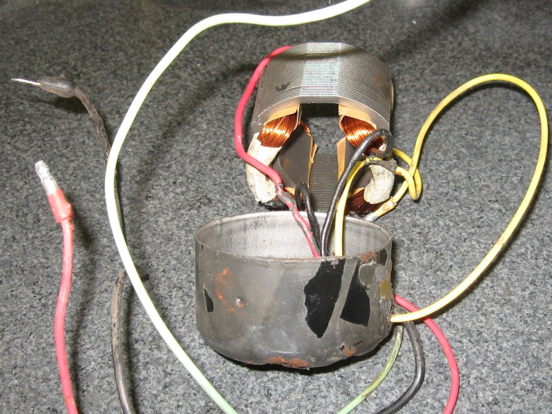
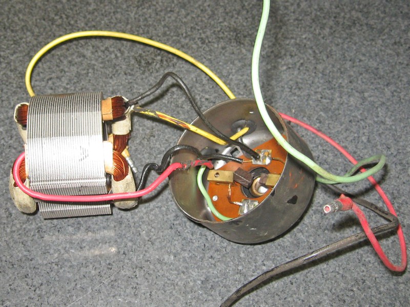
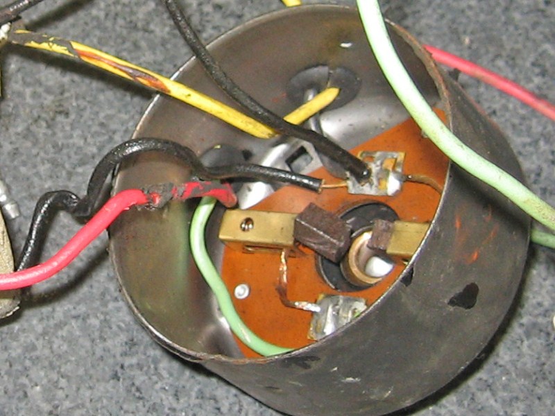
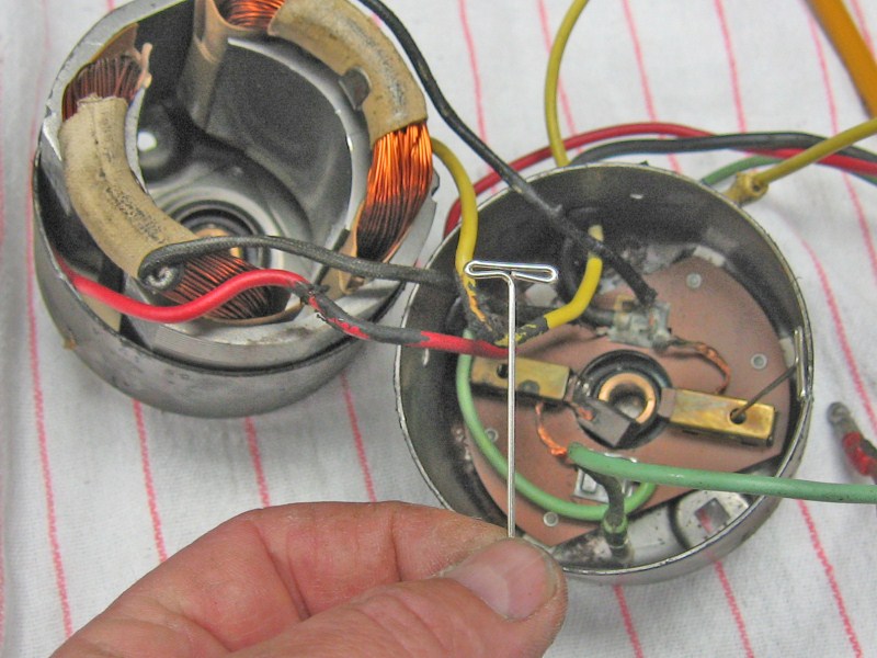
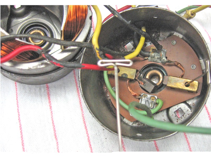
This is an excellent image showing the brush holders and solder-pad connections.
Ford kept the integrity of using colored wires for positive leads and Black for
all ground wires.
|
Picture #9
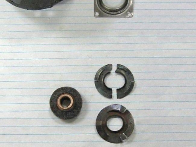
This image shows the sintered oilite bearing (on the left) with a surrounding
felt 'oiler'. The reason it is out of the nose bearing holder (top) is
because the motor shaft had a bur and excessive hammering destroyed the bearing
spring. The replacement spring is on the bottom right. Normally,
this bearing assembly is riveted inside the shell and should not come apart.
|
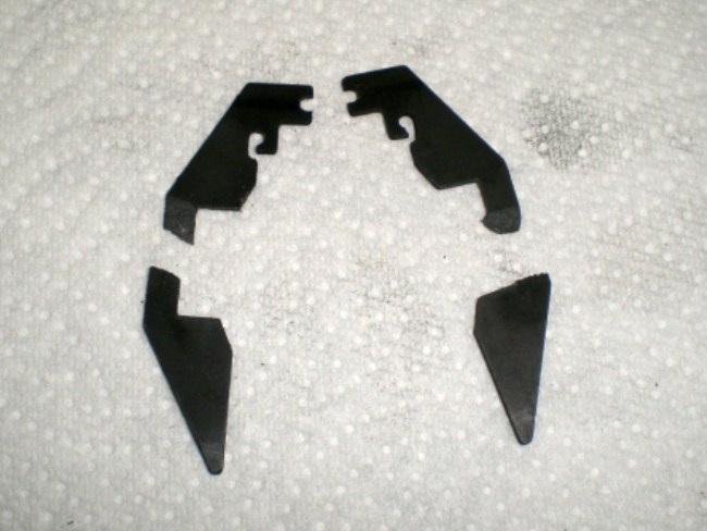
Picture #10 (from Mike Gaffney (gaffney1951))
This is a broken brush holder plate from a pre-1960 motor. Mike used epoxy
to repair it..
|
|
|
|
|
|
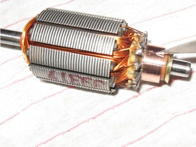
Picture #16
This armature was cleaned, turned down on a lathe. Notice the copper
commutator segments nearly touch each other? It's important to keep the
copper separated and to undercut segments by removing micarta between them with
a scraper.
Time to reassemble and paint this motor. Below is the
electrical schematic (including the switch). The motor is shown within the
dashed lines.

|