Announcement

Collapse
No announcement yet.

Eric's 1960 T-Bird

Collapse
X
 
  • Time
  • Show
Clear All
new posts
  • OX1
    Super-Experienced
    • Feb 10 2016
    • 557

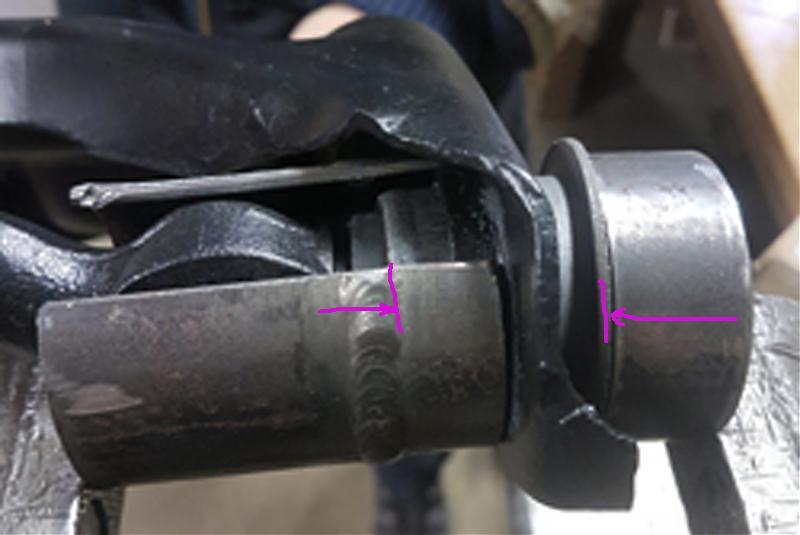
    So in your pic, you are in to shoulder?
    Appears you are not far enough in.
    (based on how much I see inner metal tube
    into A-arms on both sets of my pics)
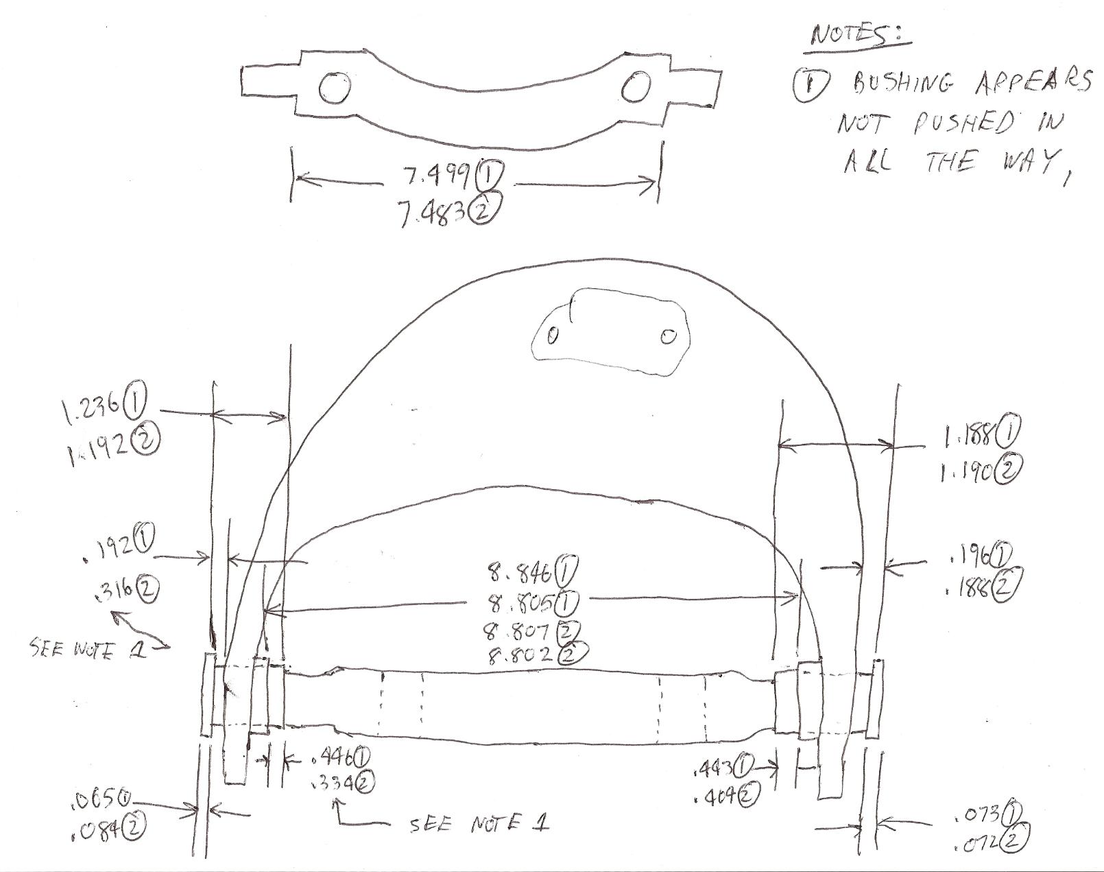
    Maybe bushings were made wrong.

    Can you give me a dimension on bushing here?
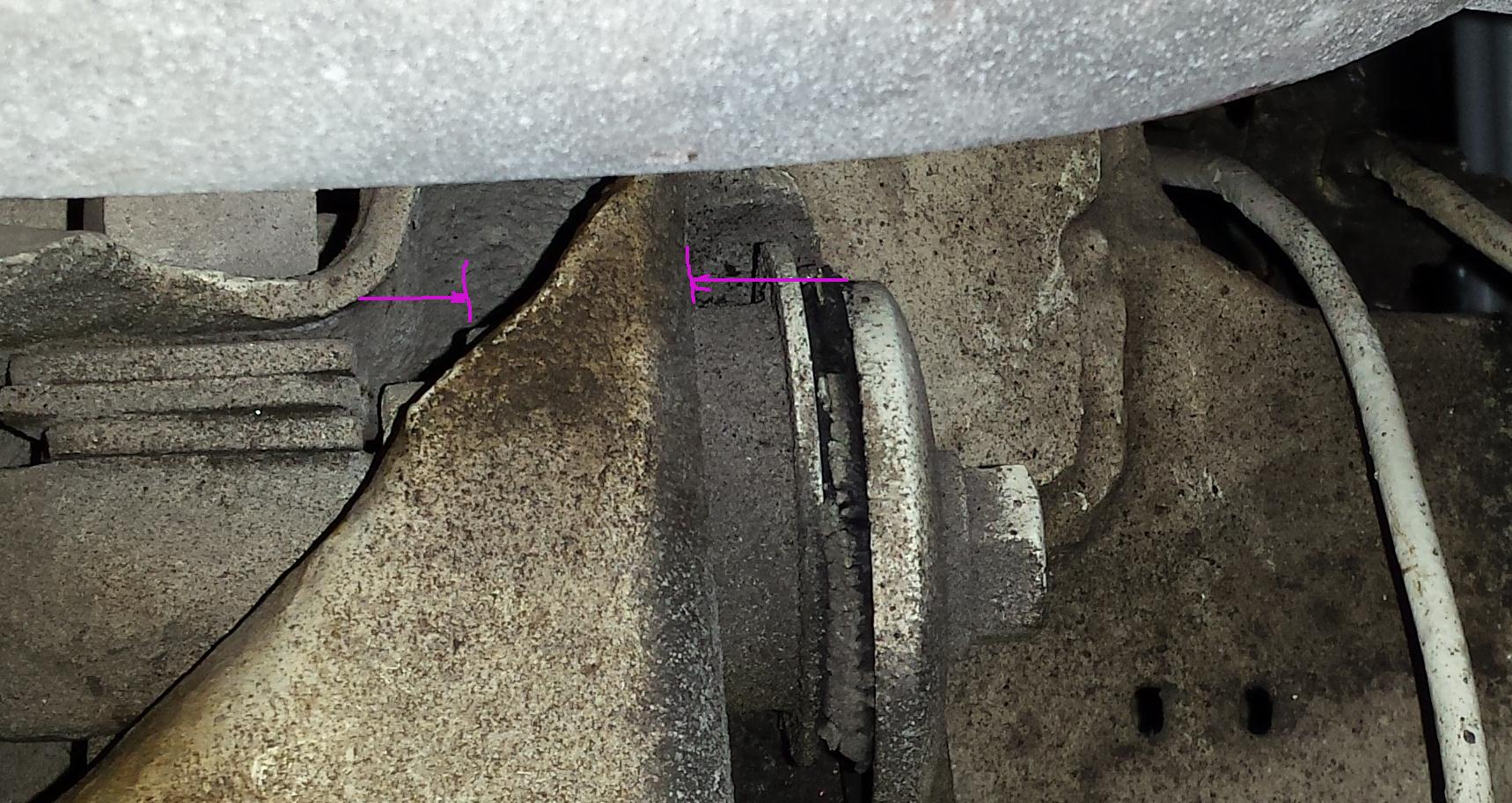


    and here


    and on A-arm here?


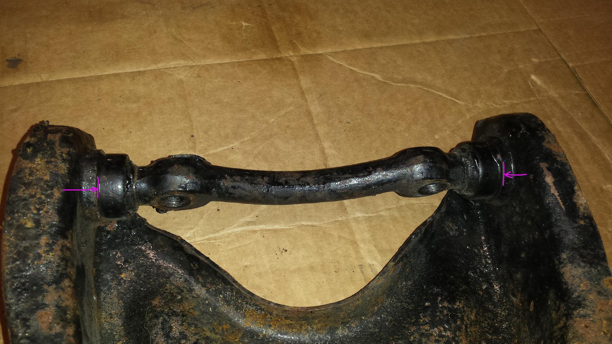
    I have knuckle and A-arm assemblies in attic.
    I can measure all that stuff in the morning,
    we can compare.
    59-430-HT

    Comment

    • OX1
      Super-Experienced
      • Feb 10 2016
      • 557

      Originally posted by simplyconnected
      Henry, you have great pictures. Can I use them for reference?
      Sure, my main directory for the bird is here
      if you want to look through anything else.


      59-430-HT

      Comment

      • mh434
        Comfortably numb
        • Jan 10 2017
        • 178

        That's a great set of photos.

        Jon
        Jon
        Deepest Hertfordshire
        Old enough to know I'm right...
        1960 Hardtop T'bird
        1961 Hotchkiss M201

        Comment

        • simplyconnected
          Administrator
          • May 26 2009
          • 8787

          September 28:
          Originally posted by simplyconnected
          ...The proper procedure MUST be followed or you will soon be doing this job again. - Dave
          September 28:
          Originally posted by simplyconnected
          ...Pounding the new bushings in is easy. Don't go past the ribbed stops and make sure you have the pivot shaft correctly inside the control arm before you start...
          October 24 Picture captions show the stops:
          Originally posted by simplyconnected
          ...After you seat your lower control arm bushings TO THE SHOULDER STOPS, the car body bolts and shims hold the inner bushing sleeves solid (so they can not rotate or move)…Examine both of these bushings:


          This is a 1955-1960 lower bushing. Notice it does have many protrusions that ARE a shoulder stop. (They also prevent the outer shell from rotating.)


          Here is a 1958-60 upper bushing. It also has a shoulder stop but it looks slightly different...
          October 30:
          Originally posted by simplyconnected
          ...Good pictures of the original setup will reveal an air gap between the control arm and the bushing flanges. These bushings do NOT seat all the way to the flange. They stop at the 'step' because the step (or shoulder) is too large to fit inside the control arm hole.

          When you insert new bushings in the upper control arm, the pivot shaft must be inserted FIRST, so it is trapped between both bushings. You will see that the bushings will stop on the pivot shaft before the outer shell flanges go too far... I have a press but I no longer use it for control arm bushings because it isn't needed.
          November 2:
          Originally posted by Eric S
          ...No shims required. I simply adjusted with the bushings as I had to take them slightly back to fit the assembly...

          Now the uppers.
          After a good numer of hammer strikes, 2 hits in the hand, I went to a local shop with bigger hammers and it do not goes in any better...
          ...Now, the bushings are all the way to the shoulder (not the flange) and I still have about 10mm/.40" of available space on the inner shafts...
          Originally posted by Eric S
          There is no room for shims. To use shims Will require To push bushings back. I Will mesure old bushings and shims...

          Re. Upper
          I Will check old ones but do I have to push bushings to the shoulder or PASS IT?
          ...Tried this wrong method trying to find solutions after the hammer method failled to pass the shoulder.
          Lower bushings enter from the INSIDE of the control arm. When seated to the stops AND shims are in place to take up any space in front, Both 7/8" bolts hold the lower control arm to frame members, preventing the arm from moving front-to-back. Now that you inserted the bushings past the stops I am afraid the bushings will move in the lower control arms. They simply are not centered properly.

          Originally posted by Eric S
          ...I still do not know if I need to pass the shoulder into the arm???
          Again the bushings at HarrysTbird has no shoulder. Those at Bird Nest do have one and I am afraid (based on the hammer strikes I did) that I can not pass the shoulder with this simple OEMTools...
          Originally posted by Eric S
          ...Not having to pass this shoulder (which is what I am asking for days) would explain why I can not do it...
          Eric, I have explained in detail, how far the bushings go into the arms back in September. I also provided pictures. You have forced them past their shoulder stops even though you say it was hard to do with hammers. That's why I use hammers. A 20-Ton press or a vice will force the bushings passed the stops. The tool you ordered will break or bend before the bushings go past the stops. That should indicate, something is wrong and you really need to stop pushing.
          This is not technical. You have bushings you removed to compare with the new. Measure the outer shells. I bet they are the same. Why? Because Ford used your bushings in millions of the following cars:

          EDSEL CITATION 1958
          EDSEL CORSAIR 1958-1959
          EDSEL PACER 1958
          EDSEL RANGER 1958-1960
          EDSEL VILLAGER 1959-1960
          FORD CLUB 1955-1956
          FORD COUNTRY SEDAN 1955-1962
          FORD COUNTRY SQUIRE 1955-1956
          FORD CUSTOM 1957-1959
          FORD CUSTOMLINE 1955-1956
          FORD DEL RIO WAGON 1957-1958
          FORD FAIRLANE 1955-1962
          FORD GALAXIE 1959-1962
          FORD MAINLINE 1955-1956
          FORD PARK LANE WAGON 1956
          FORD RANCH WAGON 1955-1962
          FORD SKYLINER 1955-1959
          FORD SQUIRE 1956
          FORD STARLINER 1960
          FORD SUNLINER 1959
          FORD THUNDERBIRD 1955-1960
          FORD VICTORIA 1955-1960
          LINCOLN CAPRI 1952-1957
          LINCOLN CONTINENTAL 1958-1960
          LINCOLN COSMOPOLITAN 1952-1954
          LINCOLN CUSTOM 1955
          LINCOLN PREMIER 1956-1957
          MERCURY COLONY PARK 1957-1962
          MERCURY METEOR 1961
          MERCURY MONTEREY 1954-1962
          MERCURY VOYAGER 1957

          I sincerely hope your upper control arm is not splayed out from forcing bushings into or out of the sheet metal arm. - Dave
          Member, Sons of the American Revolution

          CLICK HERE to see my custom hydraulic roller 390 FE build.

          "We've got to pause and ask ourselves: How much clean air do we need?"
          --Lee Iacocca

          From: Royal Oak, Michigan

          Comment

          • Eric S
            Super-Experienced

            • Jun 10 2018
            • 1054

            Sorry Dave
            I asked for days if I have to PASS or NOT TO PASS this shoulder and I still have no clear reply.
            Despite the fact I asked several times if I have to PASS this shoulder or not, I did not get a firm YES or NO reply. I am maybe not smart but I read several times all the messages and can not make a clear reply out of the information received. And yes you said on 10/30 the step (or shoulder) is too large to fit inside the control arm hole.

            Subsequent messages led confusion ;
            When I said
            I am at a place where I can not drive the bushings more (The local shop said they can use a press but they felt it was all the way in) but the inner shaft still moves left to right.
            You replied You should look for a shop with more experience because this job is not technical.
            So I thought it may be needed to be driven pass the shoulder whereas I was at the end of the job with bushings in place...

            That means they squeeze down in diameter.
            Could be understood as the shoulder will squeeze?!

            On lowers :
            Don't go past the ribbed stops and make sure you have the pivot shaft correctly inside the control arm before you start...
            I don't have ribs on the upper bushings but a shoulder stop !


            Lower control arm bushings TO THE SHOULDER STOPS, the car body bolts and shims hold the inner bushing sleeves solid (so they can not rotate or move)[/I]
            Do you mean RIBS or shoulder stop at the flange?
            If I don't enter the ribs in the arm, then they will do nothing at preventing rotation if they remain outside?

            it does have many protrusions that ARE a shoulder stop. (They also prevent the outer shell from rotating.)
            Again if you stop at them they do not enter to prevent rotation.

            You will see that the bushings will stop on the pivot shaft before the outer shell flanges go too far...
            It does not reach the shaft.

            I am sorry but my english understanding and the lack of clear and direct reply do not allowed me to understand what you meant most of the time as it brings more confusion than reply.
            On the lower arms that I likely pushed too far, the small ribs that do NOT have to enter the arm are so small we do not felt them when I entered them in a mere vise.
            When you say that those ribs should prevent rotation, it was clear for me that they need to be forced in the arm to prevent rotation. Again the lack of simple and clear reply led me to mistakes.
            If you followed well I stopped pushing on bushings 2 or 3 days ago and I still do not understand what is happening on the upper bushings.
            Ands yes bushings dimensions on old and new are the same. See my next message.
            Last edited by Eric S; November 5, 2018, 07:53 AM.

            Comment

            • Eric S
              Super-Experienced

              • Jun 10 2018
              • 1054

              OX1

              I went to my workshop and made some measures. I missed that one though http://luxjo.supermotors.net/59%20T-...RMS/ERICsc.jpg

              Original and replacement parts seems to match.
              The dimensions showed on the bushing's pictures are replacement's measures. I added the originals' measures on the text.

              As on Lower, it looks like the ribs do not have to enter the arm so taking the bushings back (or having new ones) seems to be the way to do, and so shims will be then needed.
              Attached Files

              Comment

              • OX1
                Super-Experienced
                • Feb 10 2016
                • 557

                Dimensions.............


                The inner dimension on A-arm, I would measure it in multiple spots.
                It appears the sheet metal is not always uniform.
                The 8.846 is more an anomaly, IMO. The other 3
                dimension (8.805, 8.807, and 8.802) are most likely
                closer to spec (and almost dead nuts to each other).

                Can you measure your other A-arm there?
                Are you having this problem on both sides?
                59-430-HT

                Comment

                • Eric S
                  Super-Experienced

                  • Jun 10 2018
                  • 1054

                  Yes both arms are the same with roughly same gap at inner shaft.
                  I measured both arms at 8.85 and 8.95 on a single spot.
                  Did your circle numbers shows different spots or different arms?

                  I am heading to the work shop to take more measures.

                  Comment

                  • OX1
                    Super-Experienced
                    • Feb 10 2016
                    • 557

                    Originally posted by Eric S
                    Yes both arms are the same with roughly same gap at inner shaft.
                    I measured both arms at 8.85 and 8.95 on a single spot.
                    Did your circle numbers shows different spots or different arms?

                    I am heading to the work shop to take more measures.
                    1/2 in circles are different arms.
                    59-430-HT

                    Comment

                    • simplyconnected
                      Administrator
                      • May 26 2009
                      • 8787

                      Eric, I am looking at your pictures. Start with the picture on the left. The left side bushing doesn't look straight or 'square' to the shaft. In fact it looks different from side to side. How come I see inner shell teeth on the left but none on the right? Furthermore, in your next picture to the right, you show a bushing with the inner shell protruding far more.

                      Take more pictures of the OUTSIDES of both bushings.

                      Measurements of urethane mean very little to me because the urethane is designed to move or squash under the outer washers. Since bushings reference from the shoulders, take your upper control arm 'spread' directly in-line over the center of both bushings, from sheet metal to sheet metal (on the arm, not the bushing). Since the outer shell measurements should be the same, the only difference should be where the inner shell is vulcanized. To me (from this angle) it looks like one sits out farther than the other. - Dave
                      Member, Sons of the American Revolution

                      CLICK HERE to see my custom hydraulic roller 390 FE build.

                      "We've got to pause and ask ourselves: How much clean air do we need?"
                      --Lee Iacocca

                      From: Royal Oak, Michigan

                      Comment

                      • Eric S
                        Super-Experienced

                        • Jun 10 2018
                        • 1054

                        Dave

                        You can not see inner Shell teeth on the right because the shaft is in and it's where the inner moved out.

                        I Guess it may look not straight on the picture bit they are not badly NOT straight.

                        from sheet metal to sheet metal (on the arm, not the bushing) I "measured both arms at 8.85 and 8.95 on a single spot"? Ses picture of arm below. Is that where you want it measured?

                        I am not home yet and typing from Phone.
                        Will have the arms at home for further measurements and pictures (my) tonight.
                        Last edited by Eric S; November 5, 2018, 01:08 PM.

                        Comment

                        • Eric S
                          Super-Experienced

                          • Jun 10 2018
                          • 1054

                          Originally posted by simplyconnected
                          Furthermore, in your next picture to the right, you show a bushing with the inner shell protruding far more.
                          I don't see what picture you are talking about.

                          I can confirm both arms at 8.85 and 8.95

                          Below are UPPER RIGHT arm pictures
                          The flange has been wrapped trying to push on them and the inner sleeves are out.
                          Otherwise bushings are straight.
                          Bushings are in and you can see the remaining gap left on the inner shaft.
                          Attached Files

                          Comment

                          • Eric S
                            Super-Experienced

                            • Jun 10 2018
                            • 1054

                            Below are UPPER LEFT arm pictures
                            Inner sleeve has not be walked out. Flanges are somewhat abused.

                            Just thought ... I assume the inner shaft screws won't have enough force to squeeze the whole arm down onto the inner shaft??
                            Because I can see them moving when pressing just with my weak arms... I can see the gap at the shaft squeeze by about 1mm.
                            Attached Files

                            Comment

                            • OX1
                              Super-Experienced
                              • Feb 10 2016
                              • 557

                              All those bushings are up against a shoulder??
                              It looks like they should go a bit more in, just
                              eye-balling all my reference pics and the two arms I have.

                              Your arms "might" be spread about 1/16, but it
                              appears you have way more than that to go.

                              If you are up against the shoulder on all
                              those bushings, I think the shoulders were
                              put in the wrong spot.

                              I also think the tool you are using to press in,
                              is too large in dia. It should be pressing against inner
                              metal tube part of bushing, barely fitting over
                              rubber OD.
                              59-430-HT

                              Comment

                              • Eric S
                                Super-Experienced

                                • Jun 10 2018
                                • 1054

                                Yes the bushings are against the shoulder (not the flange) and can not be driven anymore.
                                I have about .40" more to do to close over the inner shaft.
                                The tube I used rubs against the urethane. It can not be much more smaller.

                                Comment

                                Working...
                                😀
                                🥰
                                🤢
                                😎
                                😡
                                👍
                                👎