Announcement

Collapse
No announcement yet.

Degree-ing a roller cam & establishing pushrod length

Collapse
X
 
  • Time
  • Show
Clear All
new posts
  • HighwayThunder
    Experienced
    • Nov 19 2013
    • 139

    Degree-ing a roller cam & establishing pushrod length

    In what order should those procedures be performed?

    Or should measuring for pushrod length be part of the degree-ing procedure (if so after what part of the procedure)?

    Thanks.

    Cheers,
    Richard, '66 Thunderbird Hardtop, 390FE, Edelbrock Al heads, Comp cam, Street Demon 650 carb. Visit my restoration blog at hwythunder.com.
  • HighwayThunder
    Experienced
    • Nov 19 2013
    • 139

    #2
    Establishing pushrod length without head gasket

    Can it be done like this...
    1. Bolt on head without gasket
    2. Adjust pushrod for zero lash
    3. Adjust pushrod 3/4 to 1 turn to add preload
    4. Measure pushrod
    5. Add compressed thickness spec of head gasket (Felpro spec says .044") .
    Or...
    1. Bolt on head without gasket
    2. Adjust pushrod for zero lash
    3. Measure pushrod
    4. Add .40" for preload
    5. Add compressed thickness spec of head gasket (Felpro spec says .044")
    Which is the preferred method?
    Richard, '66 Thunderbird Hardtop, 390FE, Edelbrock Al heads, Comp cam, Street Demon 650 carb. Visit my restoration blog at hwythunder.com.

    Comment

    • simplyconnected
      Administrator
      • May 26 2009
      • 8787

      #3
      Degreeing your crank has only to do with finding true top dead center. Many times it is performed without heads installed They simply bridge #1 cylinder with a steel strap with an adjusting screw in the middle, held down by two head bolt holes.

      Using your heads to degree the crankshaft is easier yet. Simply use the spark plug hole.

      Once you know where TDC is on your crankshaft you can then verify the camshaft angle. I always advance my cam, then I check how far I went by my degree wheel on the crankshaft. That way, if I am off a tooth it will show up right away.

      Whether your cam is for hydraulic flat tappet, roller or solid lifters, degreeing is always done the same ways.

      You suggest turning 'something' on your pushrod one turn to get .040". What is the pitch of your threads? This is important to know before telling someone that 3/4-turn is equal to .040". For example: If you are turning the adjustment screw of a pushrod and it has 24 threads per inch, then one turn equals 1" divided by 24 or .0416". If it has 28 threads per inch then 1" divided by 28 = .0357" per turn. This only works for a pushrod, not for a rocker arm with a center bolt.

      Your methods of finding the correct pushrod length leave out some important things. What is your rocker arm ratio? Forget all that and put a head gasket on. You can leave it tight but not all the way. Then, use your adjustable pushrod to measure for cam preload. Stay under .040" .030" is better than .040".

      Next, you need to know what your valve-to-piston clearance is. Will the pistons close intake valves? This can only be measured with the heads on and one set (for #1 piston) of rocker arms adjusted. - Dave
      Member, Sons of the American Revolution

      CLICK HERE to see my custom hydraulic roller 390 FE build.

      "We've got to pause and ask ourselves: How much clean air do we need?"
      --Lee Iacocca

      From: Royal Oak, Michigan

      Comment

      • HighwayThunder
        Experienced
        • Nov 19 2013
        • 139

        #4
        Dave,

        Good point about the thread size.

        I can put the head gasket on (sans sealant) to take measurements.

        The lifters are hydraulic rollers.

        I got a Comp Cams degreeing kit. The included video disk instructions in conjunction with the written instructions left me with several uncertainties wrt the degreeing procedure. For example, when taking measurements do I need to swap out my Edelbrock Performer RPM springs with the soft springs included in the klt? Why? (I'll call both Edelbrock and CompCams tech support to verify that the two systems are compatible as is.)

        I plan to go through the entire procedure at least three times to familiarize with and to verify repeatable, accurate results.

        Cheers,
        Richard, '66 Thunderbird Hardtop, 390FE, Edelbrock Al heads, Comp cam, Street Demon 650 carb. Visit my restoration blog at hwythunder.com.

        Comment

        • HighwayThunder
          Experienced
          • Nov 19 2013
          • 139

          #5
          Dave,

          One quick question. Do you think window glazing caulk would be a viable substitute for modeling clay for measuring valve-to-piston clearance?
          Richard, '66 Thunderbird Hardtop, 390FE, Edelbrock Al heads, Comp cam, Street Demon 650 carb. Visit my restoration blog at hwythunder.com.

          Comment

          • simplyconnected
            Administrator
            • May 26 2009
            • 8787

            #6
            Originally posted by HighwayThunder
            ...I plan to go through the entire procedure at least three times to familiarize with and to verify repeatable, accurate results...
            Now you're talkin'!

            All this takes is common sense, a valve spring remover tool and some feeler gauges. I realize that everyone has their own way of doing things and we use what works for us. Let's get to the basics:

            I assume you know where true TDC is on your crankshaft. Let's prove where your cam timing is set:
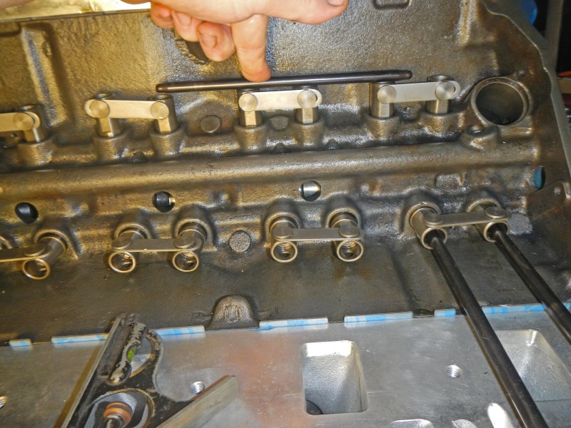
            When you rotate your crank, the #1 exhaust valve opens, then it closes. Before it closes all the way, your #1 intake valve opens. Right then, when both lifters are even (use a straight edge), between exhaust close and intake open, look at your degree wheel. It should be exactly at TDC. If it is off ten degrees, then your timing chain marks are off a tooth. Fix this first.

            In this picture I am using a straight edge across lifters from #6 because #6 piston goes up and down with #1. When 1 is on its power stroke #6 is on its exhaust stroke.


            With your cam and timing chain installed, at least one head is installed (usually the head over #1 piston) and all your spark plugs are removed for ease of turning the crank by hand...

            Valve-to-piston clearance can be measured with NO springs, which is how I do it. Just make sure your valves do not drop. The viton seals in your Edelbrock heads hang on to the valve stems pretty well but I also use a bread wrapper twist tie around the lower groove of the valve (for safety).

            Some procedures use a light spring to hold the valve up, but still allow you to push the valve down by hand. If I had solid lifters, this would work well. For dry hydraulic lifters I prefer to use all my senses, mainly my sense of touch, so I can feel the free-floating valve as I tap it against the piston with no spring pulling the valve. Remember, your hydraulic lifters are new and dry. You still need to feel when the lifter is at ZERO pre-load (when the plunger is resting on the top circlip). Light spring pressure against the rocker arm will push the plunger down, which ruins your measurement. You want the rocker arm to be still during this procedure, so you can measure between the rocker arm and the valve top.

            Let's get started. Set your exhaust valve pushrod at zero preload while pulling the valve up against the rocker arm. Once the pushrod is set and the valve has no spring, you can move the valve up and down freely with the piston down. As you slowly turn the crank, move just the valve up and down with your index finger and thumb to feel where the piston is. As the piston approaches the top, the distance you can move the valve will become shorter and shorter. When this distance is at its shortest, put your feeler gauge between the valve stem and the rocker arm (again, this requires a 'touch' because you don't want to move the plunger in your lifter). Record that number.

            Do the same for your intake valve. Remove the pushrod from the exhaust side and move it to the intake valve. Follow the above procedure. Record the feeler gauge reading when done.

            If any valve clearance between the rocker arm an valve stem is less than .080" at any point, you want to know right away. Remember, your preload is at zero, and your rocker arms have a ratio of 1:1.5. That means, if you send the preload down .040" then the lifter pumps up, the other side of the rocker arm will push down .060" on top of the valve.

            Remember I said to shoot for .020" preload but don't go over .040"? Now you can see why. In 'worst-case scenario', if your plunger pumps all the way up, you still have a small measure of safety. The valve may not close all the way for a few cycles but at least your pistons won't crash valves or bend pushrods. If you send the preload down a lot, your are inviting a very expensive rebuild. In this sense, solid lifters don't have a preload so they cannot pump up. Instead, they require ~.019" gap for valve lash.

            How you take the valve springs off is up to you as there are a few methods. I use 100-psi of compressed air to push the valve up tightly against the head, then I take the spring off from the top. Once the valve is off and I tie it up, I remove air pressure. Notice the air hose fitting in #1 spark plug hole:

            By doing it this way, I didn't have to pull the head off several times. Everything can be measured from on top. If there is a problem, THEN you take the head off. I used no clay or putty, but a much more positive tool, a feeler gauge.

            I install all my head gaskets dry and so does Ford Motor Co.

            As said, when you do 'custom changes' to an engine, these measurements are critical and must be done when the heads, head gasket, cam, pushrods and timing chain assembled and set. 'Stock' engines have already been measured. If no changes have been made parts bolt right on.
            I hope this helps. - Dave
            Member, Sons of the American Revolution

            CLICK HERE to see my custom hydraulic roller 390 FE build.

            "We've got to pause and ask ourselves: How much clean air do we need?"
            --Lee Iacocca

            From: Royal Oak, Michigan

            Comment

            • scumdog
              Super-Experienced

              • May 12 2006
              • 1528

              #7
              And if you don't have air to do it Daves method?
              A reasonable length of CLEAN nylon cord threaded in through the spark-plug hole while the piston is down at less than TDC then wound up until you can feel a bit of resistance will hold the valve in place.

              I use 3/8" cord and melt the end to prevent frayed bits from falling into the motor.

              Just remember to wind the motor the other way to ease the tension on the cord before removing it!
              A Thunderbirder from the Land of the Long White Cloud.

              Comment

              • HighwayThunder
                Experienced
                • Nov 19 2013
                • 139

                #8
                Pushrod Length Results

                Installed the adjustable pushrod in the #1 intake slot and set it to finger tight, rotatable, zero lash, hydraulic cup not depressed. Repeated in #1 exhaust slot.

                The pushrod measured 8.810".

                Adding a .040" preload would bring it to 8.850".

                Although preload can be as little as .020", I've been advised to take into consideration the thermal expansion of the aluminum heads, which will get taller with temperature slightly lengthening the distance between the rocker and the lifter.

                The question is, what would be the optimum pushrod length to order?

                Cheers,
                Richard, '66 Thunderbird Hardtop, 390FE, Edelbrock Al heads, Comp cam, Street Demon 650 carb. Visit my restoration blog at hwythunder.com.

                Comment

                • simplyconnected
                  Administrator
                  • May 26 2009
                  • 8787

                  #9
                  I think you answered your own question. All along, I suggested you shoot for .020" preload with an absolute maximum of .040".

                  I also aver that .030" is better than .040". If your measurement is a good length, go for:
                  8.810"
                  +.025"
                  8.835"

                  So, anywhere between 8.835" and 8.840" should be great. I run aluminum Edelbrock heads and rocker shafts. I don't find a difference between hot and cold as far as lifter noise. They should be quiet.
                  Member, Sons of the American Revolution

                  CLICK HERE to see my custom hydraulic roller 390 FE build.

                  "We've got to pause and ask ourselves: How much clean air do we need?"
                  --Lee Iacocca

                  From: Royal Oak, Michigan

                  Comment

                  • HighwayThunder
                    Experienced
                    • Nov 19 2013
                    • 139

                    #10
                    Intake Centerline

                    According to the degree procedure measurements, my cam's intake centerline is @ 107.75. The spec card for the cam puts it @ 106.00 .

                    The cam manufacturer has a method for offsetting the cam sprocket pin to correct for errors.

                    Is a 2 degree error serious enough to justify that?

                    Cheers,
                    Richard, '66 Thunderbird Hardtop, 390FE, Edelbrock Al heads, Comp cam, Street Demon 650 carb. Visit my restoration blog at hwythunder.com.

                    Comment

                    • simplyconnected
                      Administrator
                      • May 26 2009
                      • 8787

                      #11
                      It really depends on what you want to accomplish with this engine.

                      Notice that most cam offsets come with +, zero and - settings. That's because folks who use the engine mostly at high rpm ranges RETARD the cam. Cruisers (like myself) want as much torque at low-mid rpm range for the street, so we ADVANCE the cam.

                      Now let's put things in proper perspective... all measurements should be referenced from the crank timing. So in reality, when you advance the cam you are really retarding the crankshaft timing.

                      Confused yet? Do this; put your degree wheel on TDC so you can see precise crankshaft timing. Now, roll the crank around and watch #6 valves. Why #6? Because #6 and #1 pistons go up and down together. When #1 is on its power stroke, #6 is on its exhaust stroke.

                      If you're going in the correct direction, #6 exhaust valve will open, then it will close. Before it closes, the intake valve starts to open. During this overlap, right when both valves are dead even (use a straight edge on your rocker arms), look at your crankshaft timing. If you have chosen straight-up zero offset, your crankshaft timing should be at TDC. If you have any offset, the numbers will show up on your degree wheel. If your timing chain is off at all (like one tooth off), the numbers will show up on your degree wheel.

                      I just gave you a good method of timing your cam, even if there are NO timing marks on the sprockets. I use it all the time to verify my cam timing before buttoning up the timing cover.

                      Whether YOU put offset into the cam timing or the manufacturer does, the real numbers will show up on your degree wheel when you understand the cam/crank relationship.

                      Questions? - Dave
                      Member, Sons of the American Revolution

                      CLICK HERE to see my custom hydraulic roller 390 FE build.

                      "We've got to pause and ask ourselves: How much clean air do we need?"
                      --Lee Iacocca

                      From: Royal Oak, Michigan

                      Comment

                      • HighwayThunder
                        Experienced
                        • Nov 19 2013
                        • 139

                        #12
                        One question (for now).

                        Given that the spec is 106 degrees, would 108 degrees be considered a +2 degree advance?
                        Richard, '66 Thunderbird Hardtop, 390FE, Edelbrock Al heads, Comp cam, Street Demon 650 carb. Visit my restoration blog at hwythunder.com.

                        Comment

                        • simplyconnected
                          Administrator
                          • May 26 2009
                          • 8787

                          #13
                          ...would 108 degrees be considered a +2 degree advance?

                          It could be but not necessarily. Some cam companies 'build-in' their own advance while others do not.

                          Go through my procedure and you can verify exactly what you have and how far off it is.

                          Again, I make sure my cam is advanced by the amount I want because I know what service my engine will be used for.

                          Here's an example... Back in the '70s when Ford used 460 engines in everything, they were real dogs with terrible gas mileage. Ford purposely retarded the cam fifteen degrees to meet emissions standards of the day.

                          Let me say again, the timing marks on the chain sprockets were off by fifteen degrees from the factory. This is 'straight-up timing', according to the timing marks.

                          When mechanics corrected the cam timing, it unleashed huge hidden torque and that engine turned into a real stump puller, burning the same gas.

                          So, two degrees? The slop in a worn out timing chain will be two degrees off. You need to decide what you want this engine to do, then tune it accordingly. You cannot know where you're going until you know where you are at. This applies to all your engine specifications (including your distributor's advance curve).

                          Just because a number is written doesn't make it so. It costs no more money to verify for yourself, then you will know. - Dave
                          Member, Sons of the American Revolution

                          CLICK HERE to see my custom hydraulic roller 390 FE build.

                          "We've got to pause and ask ourselves: How much clean air do we need?"
                          --Lee Iacocca

                          From: Royal Oak, Michigan

                          Comment

                          • HighwayThunder
                            Experienced
                            • Nov 19 2013
                            • 139

                            #14
                            What's the definintion of advance vs. retard?

                            What I fundamentally don't understand is how to interpret +2 degrees and -2 degrees.

                            Adding +2 degrees to the intake centerline could be thought of as an advance (i.e., plus = forward).

                            However, since +2 degrees occurs later in the crank cycle it could be thought of as retarding the intake centerline.

                            Conversely for -2 degrees: Does minus = back = retard? Or, because the centerline occurs sooner, is it an advance?

                            It's a newbie question, and may be obvious to everyone but me. But heck, "Twenty years of schoolin' and they put you on the day shift..."

                            Thanks guys.

                            Cheers,
                            Richard, '66 Thunderbird Hardtop, 390FE, Edelbrock Al heads, Comp cam, Street Demon 650 carb. Visit my restoration blog at hwythunder.com.

                            Comment

                            • HighwayThunder
                              Experienced
                              • Nov 19 2013
                              • 139

                              #15
                              OK, that question is answered.

                              Per the spec card the design optimum for the Comp cam is 106 degrees.

                              By using an alternate keyway on the Cloyes timing kit's crankshaft sprocket, I advanced the intake centerline to 104 degrees.

                              Per SimplyConnected that should improve low-end power, optimizing the engine for a street application.

                              Comments, anyone?

                              Cheers,
                              Richard, '66 Thunderbird Hardtop, 390FE, Edelbrock Al heads, Comp cam, Street Demon 650 carb. Visit my restoration blog at hwythunder.com.

                              Comment

                              Working...
                              😀
                              🥰
                              🤢
                              😎
                              😡
                              👍
                              👎