![]()
1960 Thunderbird Sunroof (Golde Top) Sliding Roof Panel
SLIDING ROOF PANEL REMOVAL AND INSTALLATION
When performing the following operations, refer to Figs. 1 and 2.
(Left) Fig. 1 Sliding Roof Panel and Headliner (Right) Fig. 2 Sliding Roof Panel Track and Corner
REMOVAL
1. Unlock the sliding roof and slide it rearward approximately 3 inches.
2. Remove the lock handle and cup.
3. Remove the right and left hand front slide track corners by removing the four retaining screws (Fig. 1).
4. Pry the front edge of the headliner lose from the sliding roof panel.
5. Remove the headliner by carefully sliding it forward and over the front edge of the opening.
6. Move the sliding roof panel to the fully closed position.
7. Remove the eight retaining screws from the front sliders and rear slider assembly and remove the roof panel.
8. Move the rear slider assembly forward and lift it out.
INSTALLATION
1. Position the rear slide assembly in the upper slot of the slide rails and slide it to the rearward position.
2. Position and center the roof panel in the opening.
3. Install the four retaining screws, securing the rear slider assembly to the roof panel.
4. Position the front sliders in the upper slot of the slide rails and install the four retaining screws finger tight.
5. Adjust the height of the forward roof panel edge by turning the adjusting collars so that the sliding roof panel is even with the roof top. Move the sliders outward to prevent excessive sidewise movement. Tighten the four retaining screws.
6. Adjust the height of the rear roof panel edge by turning the adjusting links so that the roof panel is even with the roof top in the locked position.
7. Adjust the two slide friction adjusting screws (Fig. 2), so that the panel will remain in any position when the lock handle is turned.
8. Install the headliner by carefully sliding it into the lower slot of the slide rails.
9. Snap the headliner clips in place and install the lock handle cup and handle.
10. Install both front slide track corners with the four retaining screws.
11. Close and lock the sliding roof
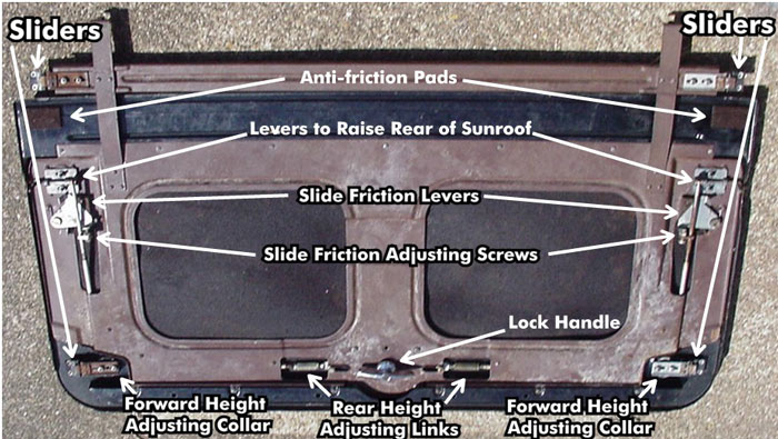
Fig 3. Inside view of sunroof
To disassemble inner panel and access inner mechanism of sunroof, remove the Phillips head screws along the forward and rear of the inner roof, the two Phillips head screws near the the forward sliders, and the two Phillips head screws along the outer edge of the sunroof near the rear levers (these may be partly hidden by the gasket).
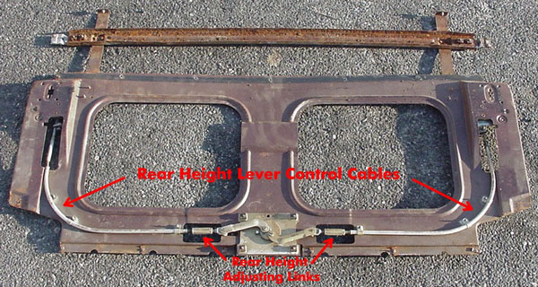
Fig 4. Inner mechanism of sunroof
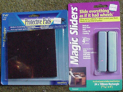
Fig 5. Anti-Friction Pad Materials. The Protective Pads are dense felt like the original material . The Pads are cut into 1.25 inch X 2.00 inch rectangles. Straighten the prongs on the sunroof so they are vertical, then remove the paper backing exposing the adhesive of the Pads and position onto the sunroof as shown in Fig. 3. Once installed, bend the prongs outward with light taps of a hammer. The Magic Sliders are more high tech material which will allow even smoother operation and are completely invisible when installed. You can use these instead of the Protective Pads. Cut the 24mm X 100mm Magic Sliders into 50mm halves for the correct size. I purchased these materials at Bed Bath and Beyond.
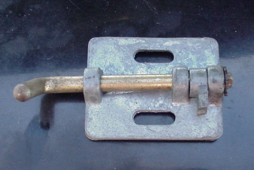
Fig 6. Sunroof lever (note broken pot metal connector to cable)
passenger side (driver side is a mirror image)
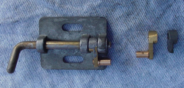
Fig 7. Sunroof lever with brass reproduction of cable connector.
Reproduction brass connector and original pot metal connector on right.
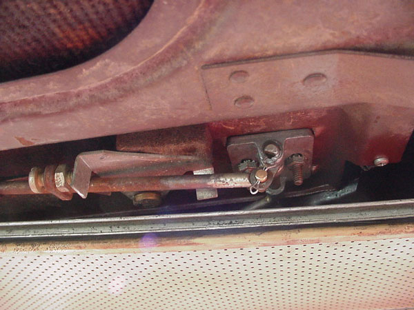
Fig 8. Passenger side cable connected to the lever assembly in unlocked position. The lever is facing forward flush against the roof in the unlocked position. The roof has been lifted by hand slightly at the rear most edge to allow view of the sunroof lever. Normally the friction lever is level with the roof rail and the sunroof lever end is hidden.
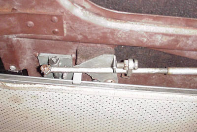
Fig 9. Driver side sunroof mechanism in locked position. Note that friction lever is held flush against the roof rail by the pressure of the slide friction lever adjusting screw.
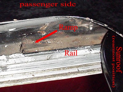
Fig 10. Rail and ramp of sunroof mechanism.
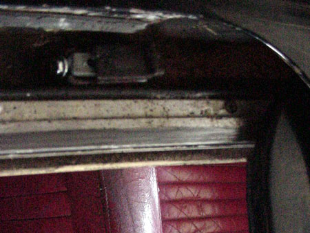
Fig 11. Rail and ramp with ramp insert of sunroof mechanism.
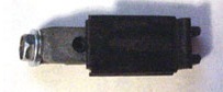
Fig 12. Ramp insert top(assembled)
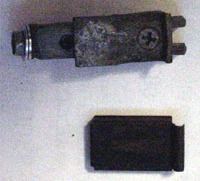
Fig 13. Ramp insert top(disassembled). Note Phillips head top pad lock screw.
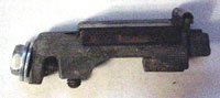
Fig 14. Ramp insert side(assembled)