
The following information was provided to us by fellow member, Gary Scott ~ kultulz.
Thank you very much, Gary!
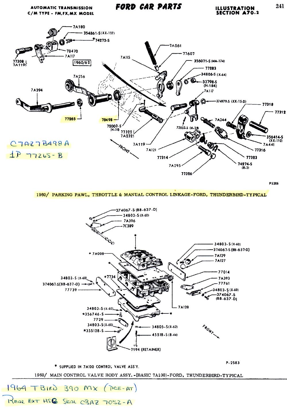
This diagram shows the parts break out for a 1960 Thunderbird FM, FX, MX model transmission. It shows the parking pawl, throttle, and manual control linkage. It also shows the Main Control Valve Body Assembly for a basic 7A100 transmission. It also contains information for a '64 Tbird.
The last half of this page describes how to perform a Shift Lever and Detent Lever Seal replacement. It was provided by
Nyles Beuchel ~ Tbird1044. Thank you very much, Nyles!
Valve body AND the shift linkage must be removed to replace the manual shaft seal. To make that easier:
SHIFT LEVER AND DETENT LEVER SEAL REPLACEMENT
1. Remove the two curved tubes that are in your way.
2. Remove the four 7/16" head bolts that hold the valve body together. (Do NOT remove the three 7/16" head bolts that hold the valve body to the case yet.)
3. Remove the four screws that hold the valve body together.
4. CAREFULLY slide the valve body section that is now loose off of the two straight tubes. (Make sure that you slide the metal spacer plate along with it. Be VERY careful to not lose the checkball that is often inside this valve body section.)
5. Now you can take out the three bolts that hold the valve body to the case and the valve body will come out.
6. You will need to remove the 1/2" head nut on the end of the kick-down lever, but make sure you hold the kick-down arm when you do this instead of torquing against inner lever. It breaks off VERY easily.
7. Remove the nut on the end of the manual lever (inside the case). When you do that, be very careful. There is a spring loaded detent in the case. DO NOT let it shoot out. When removing the shift and detent levers, they must be removed together. I had to remove the transmission mount and lower the trans to get clearance for removal.
8. Pry the old manual seal out of the case.
9. Install the new one by using a hammer and an appropriate sized socket as a driver. When the trans is still in the car, there is not much room to work. I used a nut and bolt with washers to pull the new seal into place.
10. With a small screw driver, pry the kick-down seal out of the manual arm. This is just a small o-ring.
11. Install new kick-down seal.
12. Reverse procedure to reassemble. Make sure the detent is riding on the detent notches. This is probably the hardest thing in the procedure. I started the bracket on the shift lever and put the retaining nut on hand tight. This allowed the bracket to tilt slightly, get things aligned, push the detent pin and spring up, and then tighten things up. I used a little grease to hold the spring in place for the detent pin.
13. Make sure the manual valve is engaged into the manual lever and that the kick-down lever arm (inside the case) is between the stop and the kick-down valve. This is very important when reinstalling the valve body. When you see it, it is pretty obvious how it goes together.
14. Install the three 7/16" head bolts that hold the valve body to the case and torque them to 65 inch-pounds. When installing the valve body, make sure the kick down and notch for the selector valve are properly in place. Then tighten.
15. After sliding the valve body section back onto the two tubes, make sure you start all four screws and all four bolts BEFORE you tighten any of the eight.
16. Tighten the screws snuggly and the 7/16" head bolts to 65 inch-pounds.
17. When you are done, verify the operation of the manual lever and the kick-down lever. You should feel the detents when you move the manual lever AND you should feel the spring pressure when the kick-down lever pushes the kick-down valve. You can also visually see that things are properly working.
2. It is not as complicated as all of this sounds and using this method, you don't need to remove the servos.
You might want to print this out before you start so you have it to refer to.
Created 19 March, 2013
Last Edited: 15 November, 2013
Return To Technical Resource Library
Return to Squarebirds Home