
1958-1960 Squarebird Clock Repair
By
Kim & Theo van Heel de Kok
The following is a step by step procedure, with pictures, for repairing the clock in your 1958-1960 Ford Squarebird. This information was presented by Squarebirds members Kim & Theo van Heel de Kok of The Netherlands for those who will need this information in the future. Thank you, Kim and Theo.
1. Remove the clock from the dash;
2. Check the fuse;
Determine whether or not that the fuse is broken;
3. Loosen the electrical connections;
4. Disassemble the clock;
5. Test it;
6. Clean it and test it again;
7. Reassemble it, and;
8. Put it back in the dash.
1. Clock Removal
As simple as it sounds, this is the first challenge. No worries, however! Simply pull the bezel straight from the dash and you will gain access to the screws attaching the clock to the dash. Unscrew them and the clock assembly will be separated from the dash.
2. Fuse
In the powerline for the clock (screwed to the clock body) you’ll find a connector. Twist it and it and it’ll open up. Make sure that the fuse doesn’t fall out and land somewhere behind the dash! If the clock isn’t working, chances are that the fuse will be broken. When you replace it, it’ll probably break again instantly, assuming the clock is stuck… So, on to the disassembly! The fuse is a 1AG-1 type fuse. Somewhat hard to get in the Netherlands.
3. Disconnecting from the powerlines
You can leave the short wire, with the half of the fuse holder at the end, connected to the clock body. The other connectors are for the lamps. You have to pry them out of the back of the clock body. Twisting them might loosen them a bit, but will not unscrew them, as they are pressed into the back (held by spring clamps) and not screwed in, in any way. The bayonet shaped indents which are visible on the outside are meant for fitting the lamps inside. So you just use a little sideways force to carefully pry them out. Don’t use excessive force as not to break the lamp glass when the connector gives way.
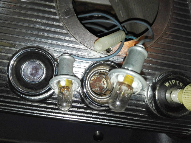
The lamp holders, showing the spring clamps
Now you’ve got the clock completely separated from the dash!
4. Clock disassembly
To be able to check the interior you will have to disassemble the clock. Basically this means taking off the back of the housing and then removing the clock chassis from the front part of the housing.
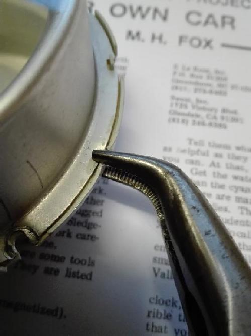
Taking the housing apart
The back part of the housing is clamped to the front part and the only way to remove it, is to carefully pry open the indentations rendering the back side loose from the front side. We used simple plyers to grasp the rim that was pushed inside and gently pry it open, using the reinforced backside for counterforce.
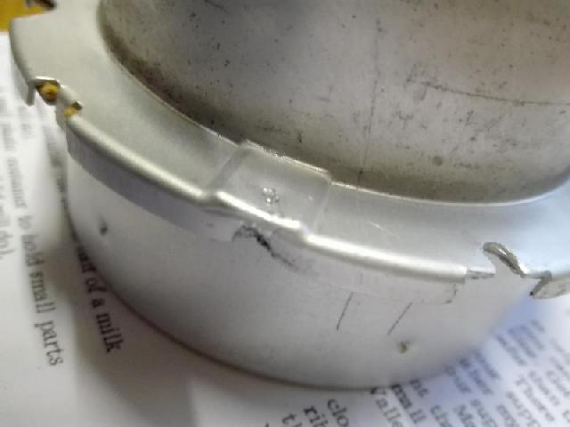
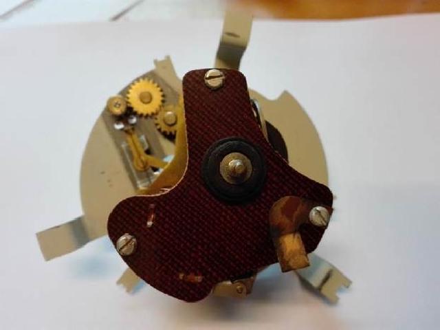
Reinforced Backside
Be gentle, take your time and pry open just enough to make it loose. After having pried open all three points you can remove the backside. Be careful not to damage the paper gasket. Should it be damaged, make new ones with the template: Clock Gasket
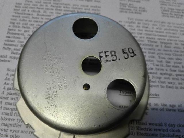
The back side of the housing
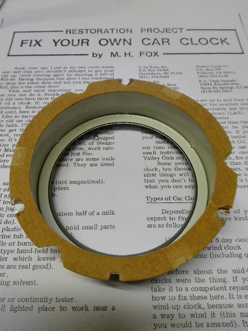
The paper gasket
Knob Removal
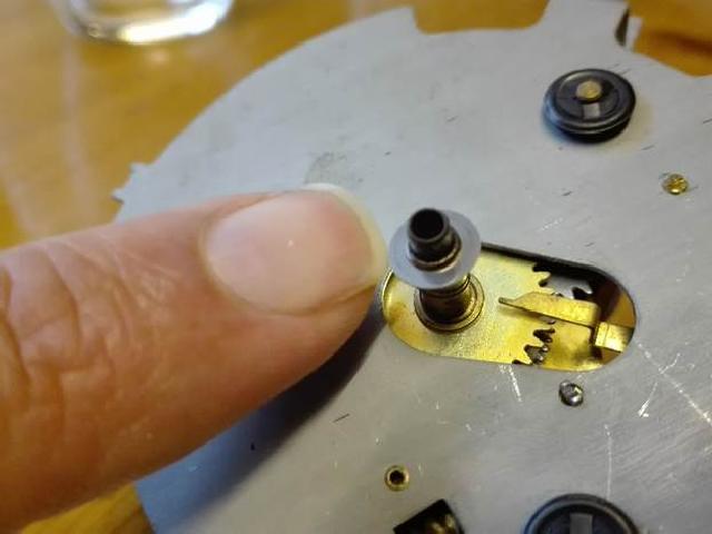
Now comes the really tricky part, as you have to remove the knob from the adjustment stem (which is still keeping the clock attached to the front part of the housing). In our case, this thing was stuck beyond belief… It has to be screwed on real tight in order to be able to adjust the clock clockwise as well as counterclockwise!
Ultimately we needed tongue-and-groove pliers to be able to prevent the stem from turning when turning the knob in counterclockwise direction with smaller pliers. Use the right amount of force to remain a grip on the stem and the knob, be careful though not to bend the stem! When thoughts about buying a new clock started racing through my mind, the knob gave way with a discernable tick/click like sound before turning gently of the threads. A few days before, we applied penetrating oil a couple of times.
After having removed the knob you can slide the stem through the hole in the glass and remove the assembly from the housing.
Hands and Dial Removal
Before you can remove the dial you have to take off the hands. The second hand is clicked in the prime axle. The minute and hour hands are crimped on the prime axle. You can remove all of them with a little more force than you would expect, but they should give way quite easily. Be sure to pull the second hand straight off and pry the other hands off with your finger nails.
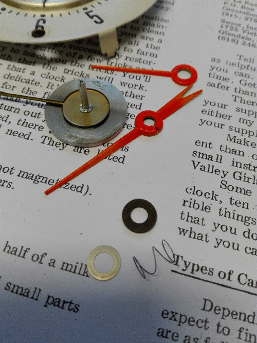
Now, you can pry open the clips that hold the little clips that hold the dial plate to the mechanism. You don’t need any tools, simply use your fingernails. Finally something easy! After taking off the dial, don’t lose the little flat ring and spring around the prime axle.
Little flat ring with spring underneath
Also remove the little gasket from the adjusting stem!
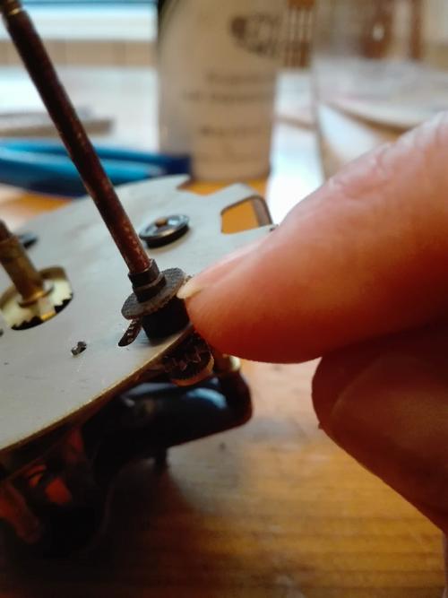
Gasket on adjusting stem
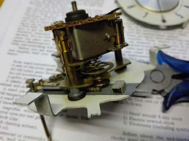
The balance wheel is seen in the center
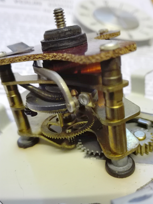
A look at the contacts
Electrical connections
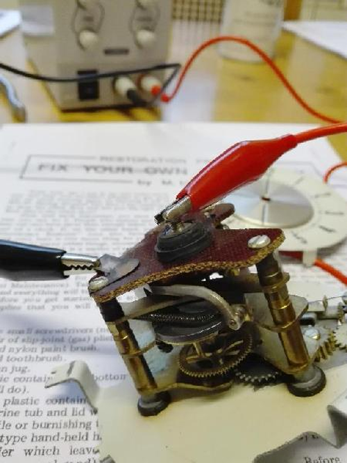
5. Testing The Clock
This is pretty much where we stopped for the moment. We cleaned the contact points and hooked the clock to a lab power supply at 12 Volts, with the contacts closed. Immediately the actuator was pushed away with a little click. When we gave the balance wheel a swing the clock started working, but the movement wasn’t strong enough to unwind the actuator and bring it in to contact again. So, conclusion: working but glued or gummed up and a little bit dirty. Cleaning and lubing must bring the solution.
6. Clean It!
If you want to clean and lube the clock yourself, these are good articles on how to do that: Look for “Clock Conversion & Repair”
TRL
Repair & Rebuild
7. Reassemble It!
8. Put It Back In The Dash
Created: 14 November, 2017
Last Modified: 15 November, 2017
To return to the Technical Resource Library,
Click HERE: TRL
Email me at: rayclark07"at"att.net (Replace the "at" with @)