Ford Instrument Cluster Voltage Regulator Assembly
Solid State Retrofit
TRIM - Dashboard Section
The original Instrument Cluster Voltage Regulator has been called by
many names including, Constant Voltage Regulator or simply, CVR.
Ford's last year for six-volt systems was in 1955, and the Dashboard
had no CVR. In 1956, Ford went to 12-volts. This was the
only year the instruments were 12-volts and again, no CVR. In
'57, Ford quickly went back to using six volts for all the gauges,
corporate wide, and they remain as such today.
The OEM CVR works much the same as a turn signal flasher with three
leads: One goes to Ignition power, one lead to ground, and the other
to the gauges. So the original pulled 12-volts through a
resistance wire that was wrapped around a bi-metal strip, to ground.
As the bi-metal strip got hot, the normally closed contact would
open, then cool and close, over and over as long as the key was
turned on.
The assembly comes with an adjustment screw (that is painted), but
none of the manuals explain how to adjust the timing. A 6-volt
average of 12-volts would be an on and off time of 50%, or 50% duty
cycle. I put my Fluke meter on one and checked for Hz.
It was all over the map, from 0.4-seconds to 1.4" and very irratic.
I realize this was a cheap way to get 6-volts back in the day.
Now we have much better methods.
For the scope of this site I will retrofit a 6-volt Solid State
regulator into the original metal case, showing each step.
Then I will test it.
 #1
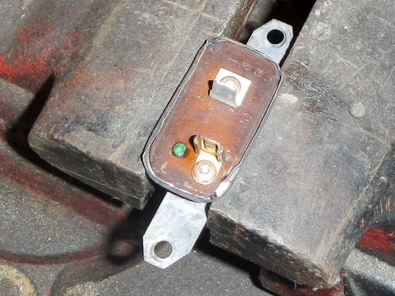
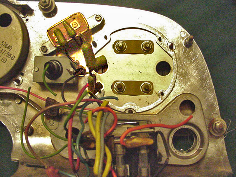
#1
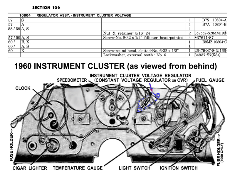
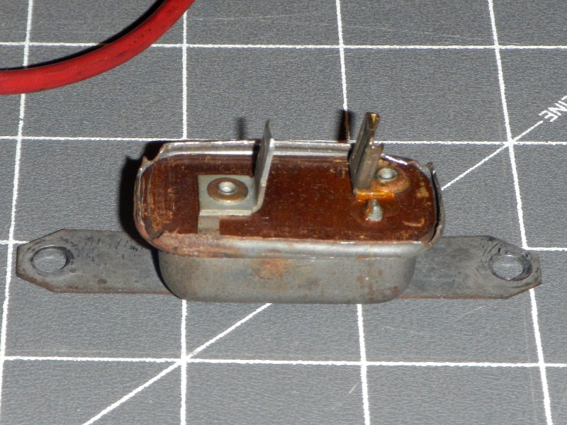
This is the location and part numbers for Squarebird CVRs.
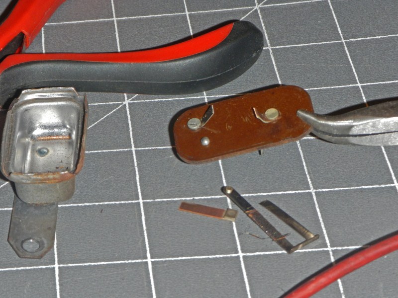
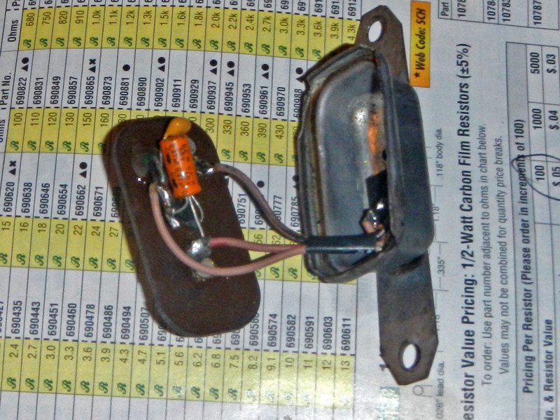
 #2
#2
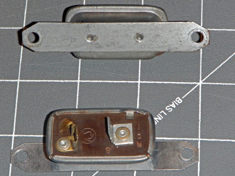
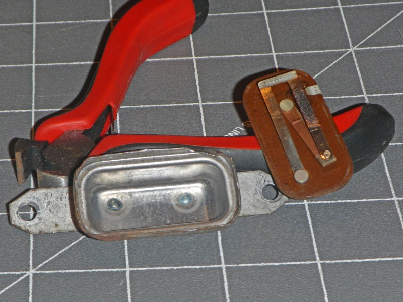
These are two broken units, removed from different Squarebirds.
 #3
#3
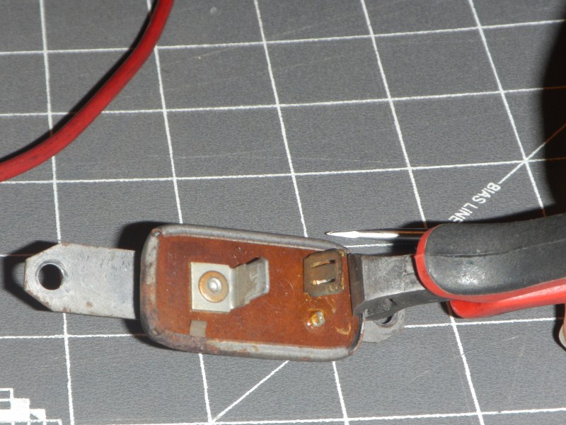
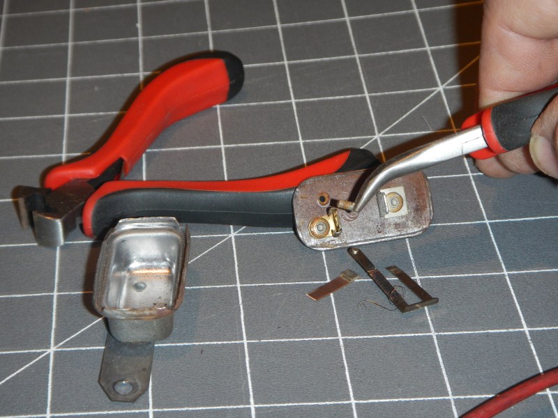
The first job is to open the case.
 #4
#4
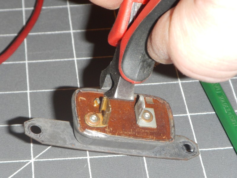
I'm working on opening the third side.
 #5
#5
That's it. Let's see the inside...
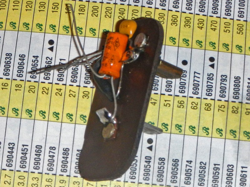
 #6
#6
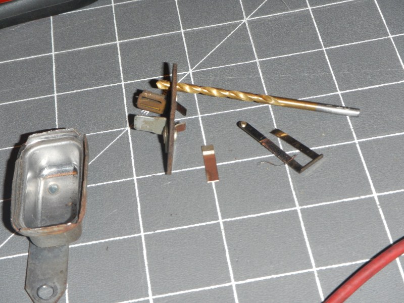
The bi-metal strip on the right side is wrapped with very
small resistance wire which causes it to heat. This one is
burned open. Notice the end of the tiny wire goes under an
edge clip for the ground connection.
 #7
#7
Notice the 'adjustment' jack screw and the grounding clip.
This is a recipe for disaster.
 #8
#8
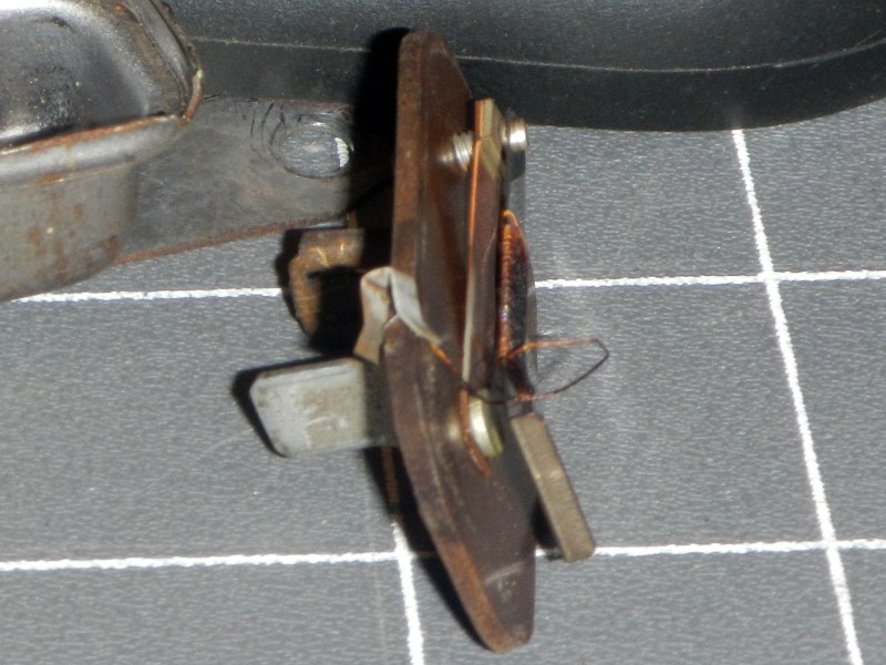
One last look before I tear into it.
 #9
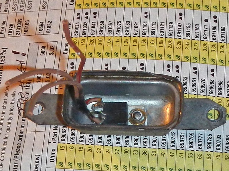
#9
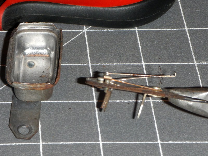
The original connectors are tight in the rivets.
Notice I left a stub of metal after tearing the arms off. I
will tin these and solder my 12-v 'Input' and 6-v 'Output' wires to
them.
 #10
#10
I removed the adjustment screw. This is a perfect hole to
put a green LED to show the 6-v side works.
 #11
#11
All holes I drill will be 1/8".
 #12
#12
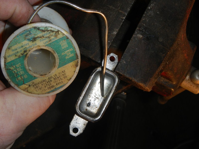
The solder I use (AQUABOND by KESTER) contains NO lead and is
Silver Bearing. Yeah, it's the good stuff.
I am creating a flat, smooth 'bed' at the bottom of this stamping
(for the regulator). They projection spot welded the bottom
strap to the case, leaving dimples in the surface.
Time to talk about the Electronics...
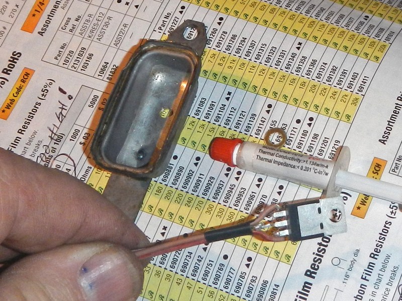
 #13
#13
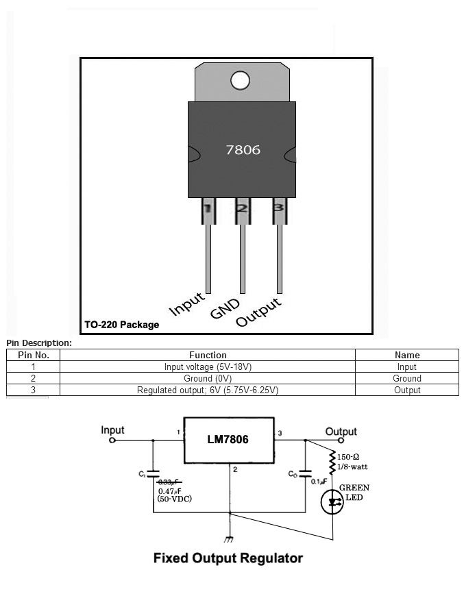
This is a Fixed Output, LM7806 Voltage Regulator in a TO-220
case. The center leg (2) is also electrically connected to the
metal backing with the mounting hole. So conveniently, the
case will be our NEG.
All I need is two capacitors (C1
= 0.47uF)
and a very small LED with a dropping resistor (150-ohms). I am using the
correct 0.1uF for C0,
but a larger cap for C1
because car electrical systems are notorious for voltage spikes
and drops.
 #14
#14
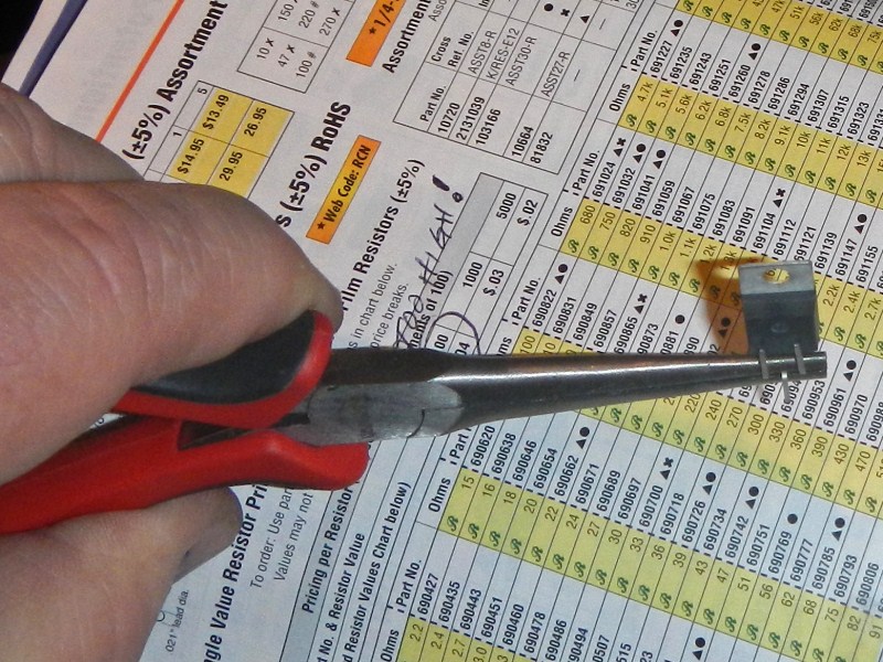
To prevent metal fatigue, it's important to hold the leads with
pliers, away from the case, while bending the leads. If
disaster strikes and the leg comes off, a 'tab' will remain for an
acceptable solder connection.
 #15
#15
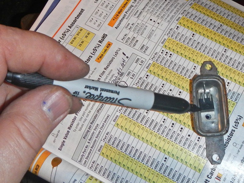
Place the TO-220 in the housing and mark the 1/8" hole.
 #16
#16
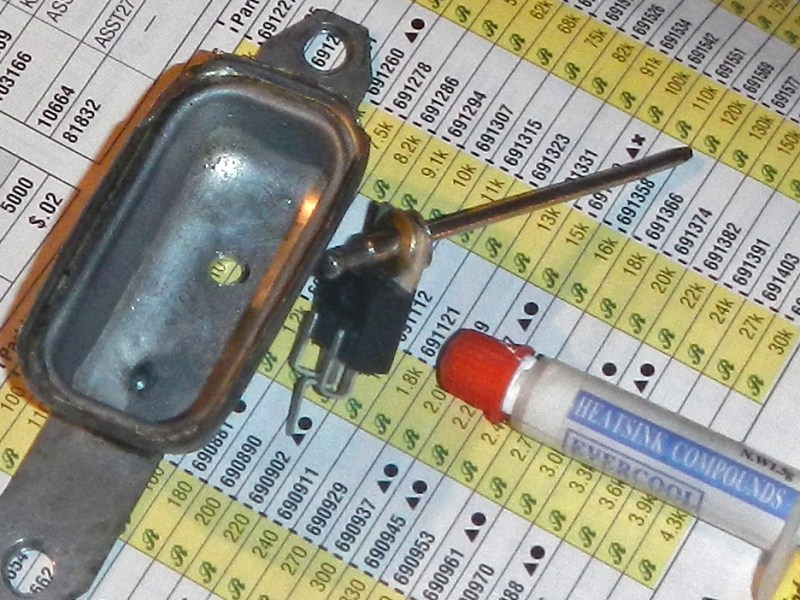
These are the setup parts: A 1/8" pop rivet, a 1/8" hole brass washer, and
heatsink compound. Now I am ready to wire.
WIRING
 #17
#17
Solder three short leads onto the regulator. It's hard to
see but I marked the power leads, red (12-v) and black(6-v).
 #18
#18
Use plenty of heatsink grease and pop rivet the parts together.
Set it aside for later.
 #19
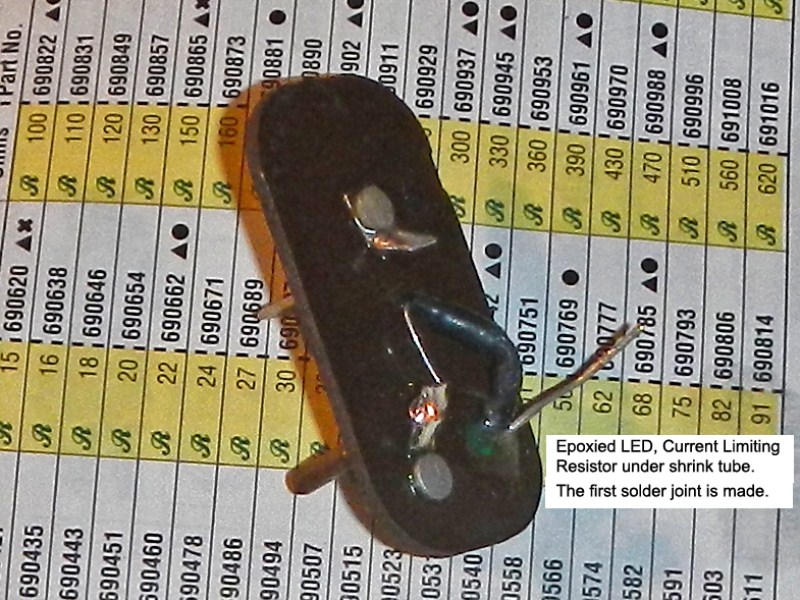
#19
I used epoxy to mount the LED. After it cured I added a
dropping resistor (150-ohms@1/8-watt), heat shrink-ed the 6-volt leg
and soldered it to the output post. Notice the NEG leg is
sticking up.
 #20
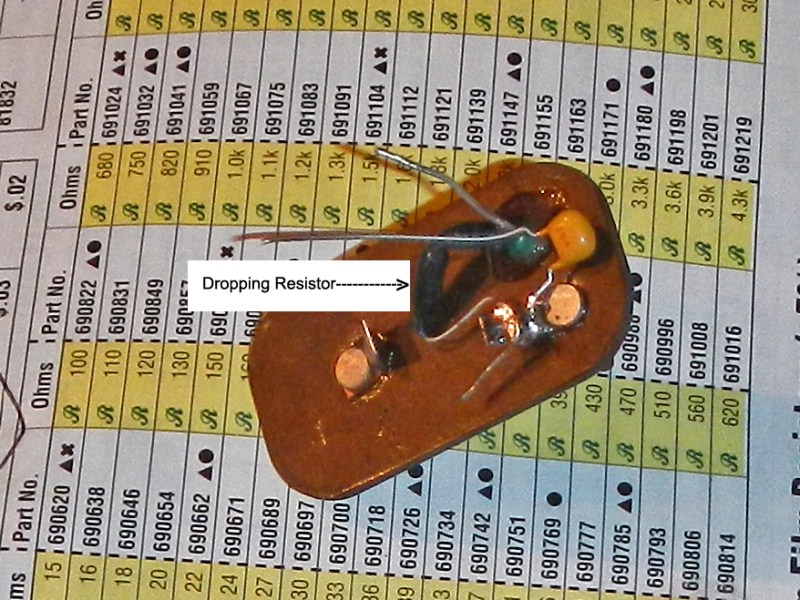
#20
I added the 0.1Uf
capacitor to the same output tab. Now I have two NEG legs
sticking up.
 #21
#21
The (0.47uF@50v) Input cap neatly nestles in the middle. See how all
three NEG legs stick up together?
 #22
#22
Time to solder all the NEG leads together, then solder the power
leads to their tabs. The next one I assemble will have shorter
wires, but notice that half of the 'can' is empty. That is the
portion where the bulky parts fit into.
 #23
#23
 #24
#24
I used a wide chisel to hem the edges.
TESTING
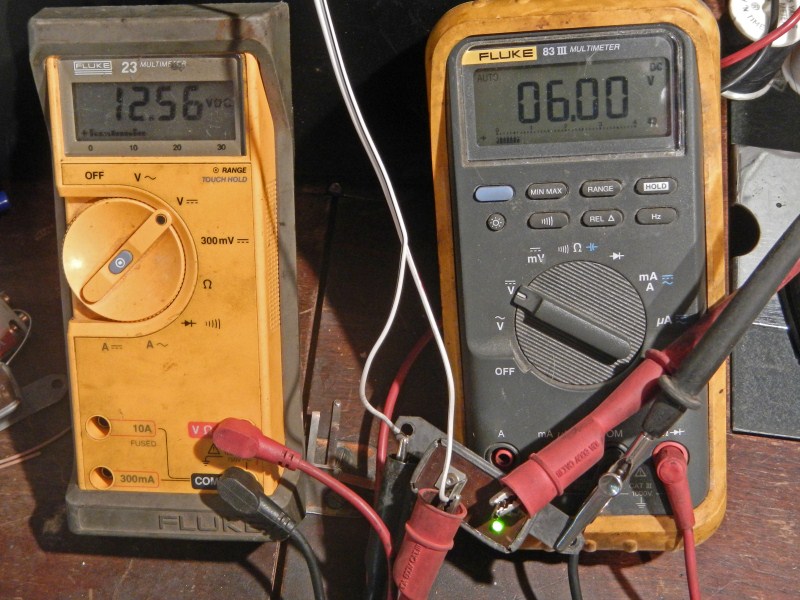 #25
#25
Here it is... 12.56-volts from a car battery (IN), and a solid
6.00-volts (OUT).
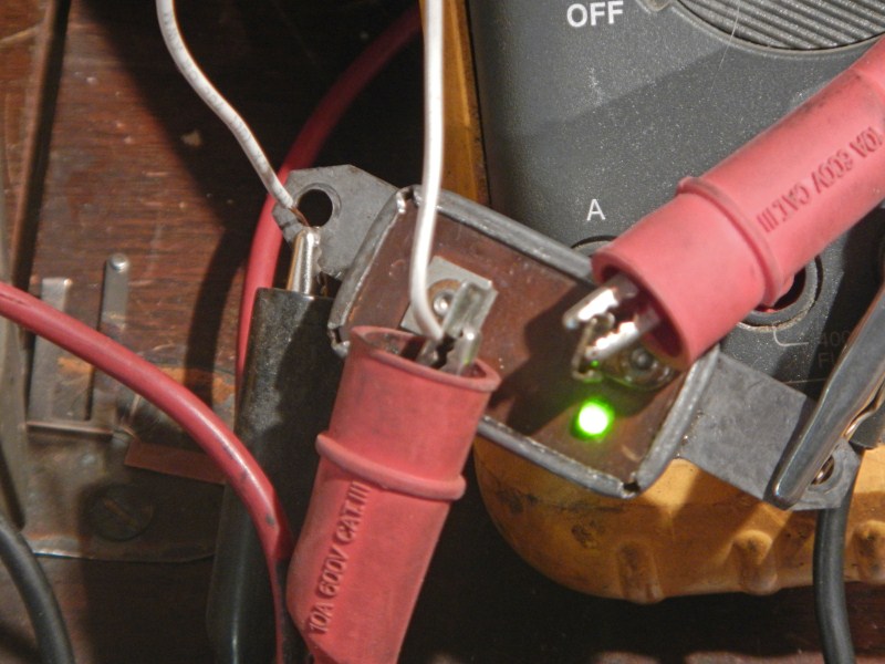 #26
#26
The indicating LED looks like it belongs there.
 #27
#27
I want to extend a special "THANKS" to Yellowrose (Ray Clark) and NYsquarebird58 (Marcelo Laviano) for sending me
their old CVR units. Without them, I was stuck with the electronics in a breadboard,
but no real way to test it. Now, we can save our Squarebird.org members at least US$25
over retail price.
RETURN to TOP of PAGE